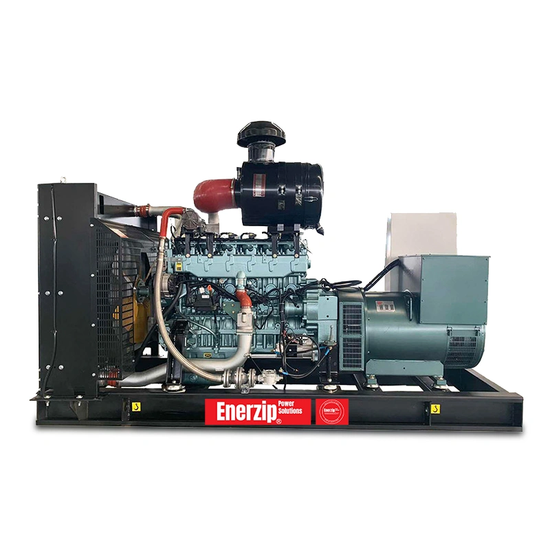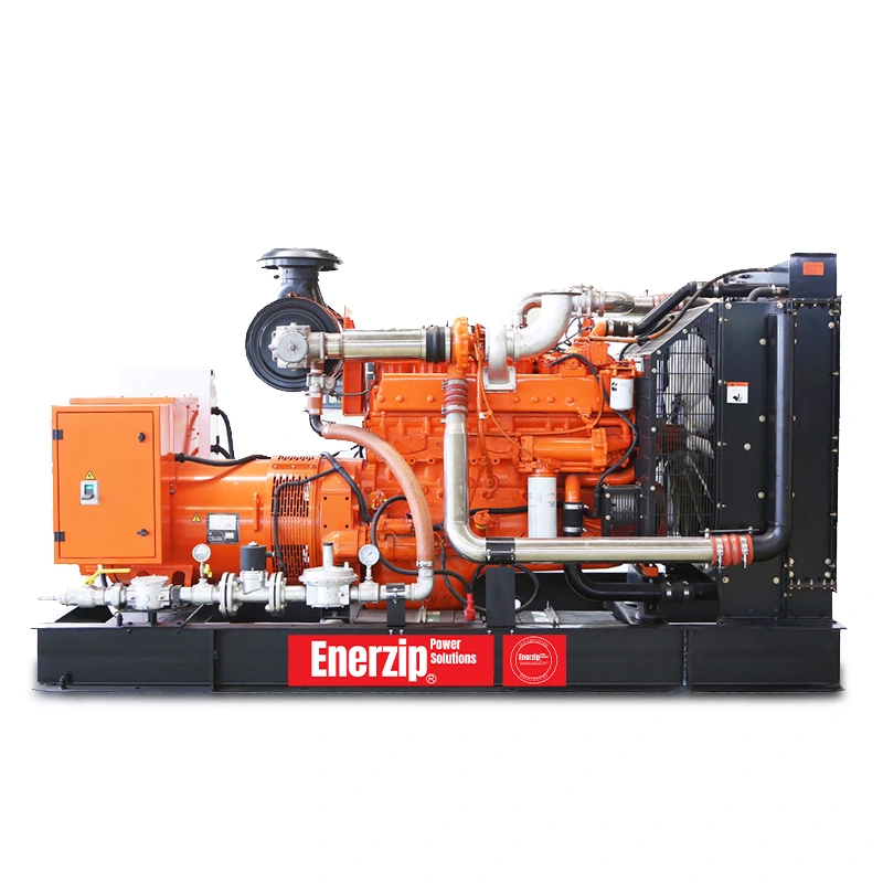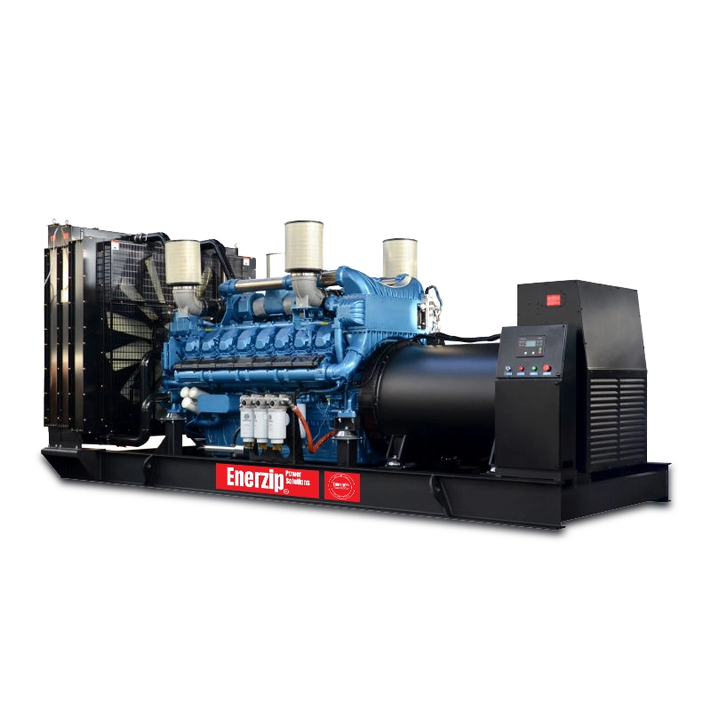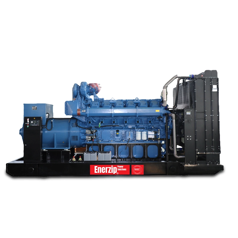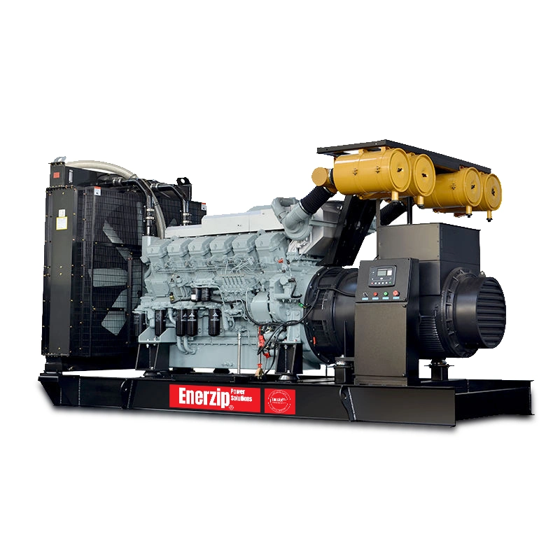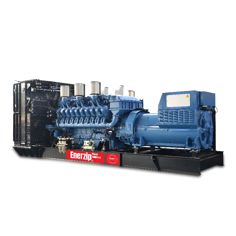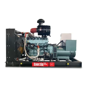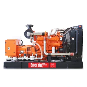
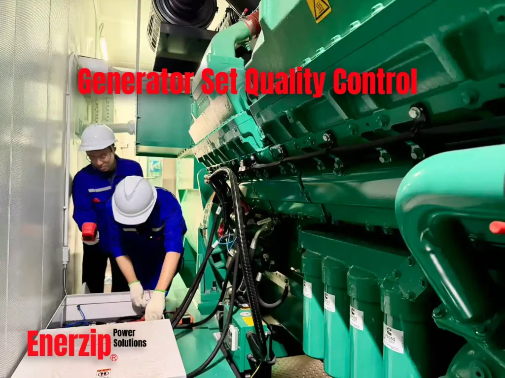
Enerzip manufactures generator-set packages and integrates standby power systems.
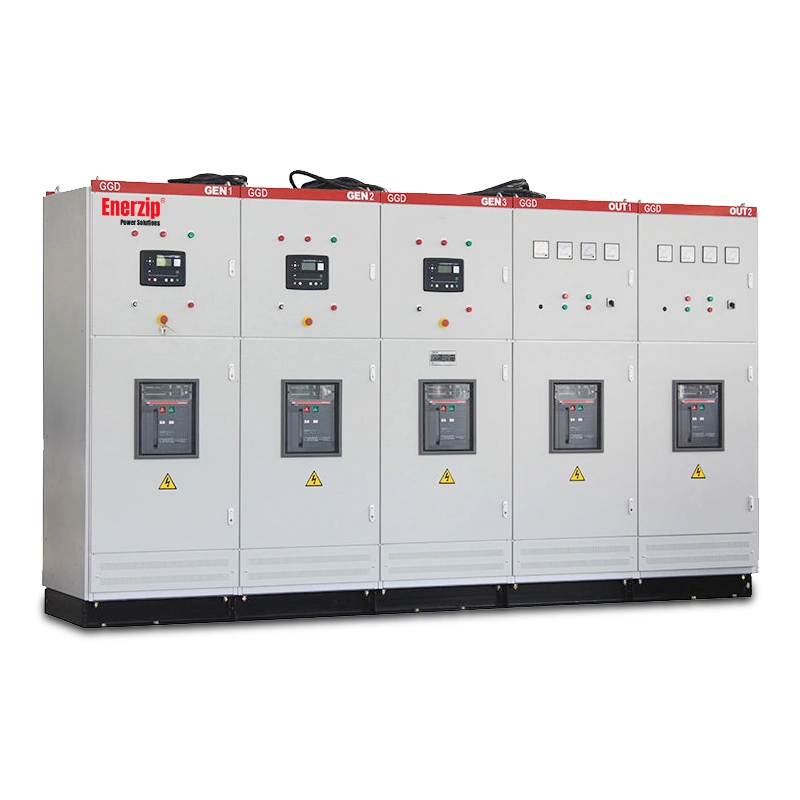
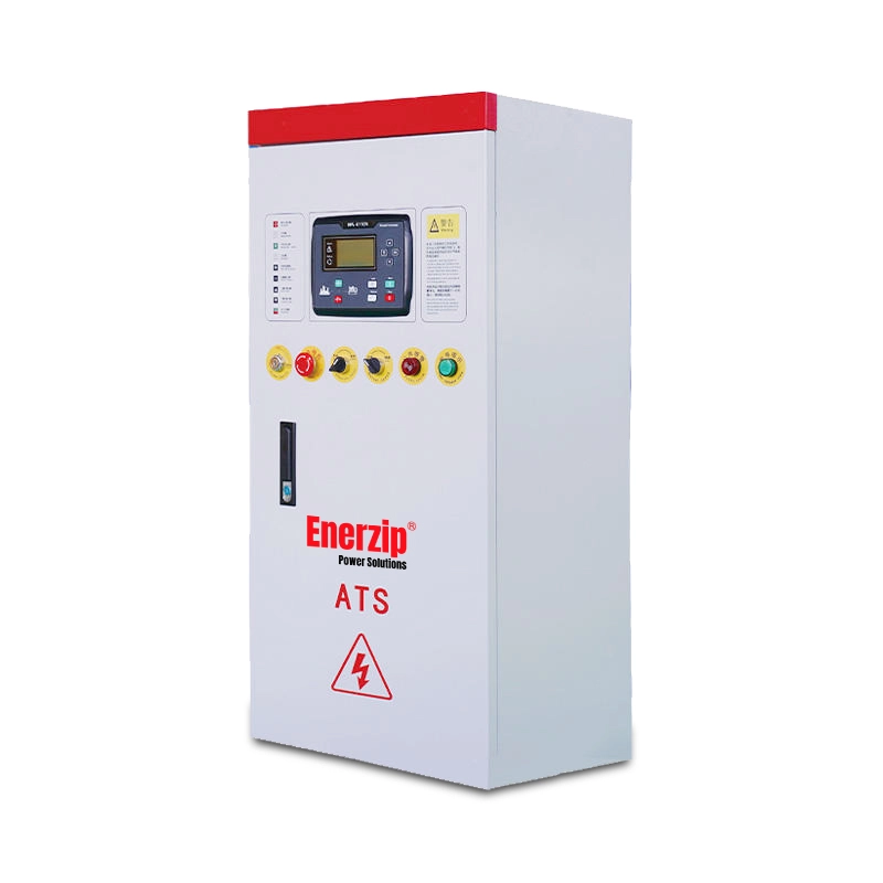
Enerzip’s manufacturing scope covers generator-set base frames, fuel tanks, silent enclosures, containerized packages, ATS panels, generator distribution panels, paralleling control panels and project power-distribution equipment. Enerzip completes package engineering, fabrication, mechanical assembly, electrical wiring, control configuration, inspection and factory testing.
Engines, alternators, controllers, circuit breakers and specified electrical components are purchased from the manufacturers stated in the approved bill of materials.
The approved technical specification, drawings, bill of materials, inspection and test plan and purchase contract define the requirements for each order.
1. Quality-Control Responsibility
The original component manufacturer is responsible for the design, manufacture, certification and original product warranty of its engine, alternator, controller or electrical component.
Enerzip is responsible for:
- Generator-set package engineering
- Verification of purchased components
- Base-frame manufacturing
- Fuel-tank manufacturing
- Silent-enclosure manufacturing
- Containerized package manufacturing
- ATS-panel manufacturing
- Generator distribution-panel manufacturing
- Paralleling control-panel manufacturing
- Power-distribution equipment included in the contract
- Mechanical assembly
- Electrical wiring
- Control programming
- Equipment-interface coordination
- Production inspection
- Operational testing
- Tests stated in the approved inspection and test plan
- Correction and closure of non-conforming items
- Final shipment release
2. Production Documents
Production starts after approval of the applicable documents.
The production documents consist of:
- Customer order
- Technical specification
- Generator-set data sheet
- Approved general arrangement
- Electrical schematic
- Single-line diagram
- Bill of materials
- Control sequence
- Inspection and test plan
- Factory acceptance test procedure stated in the contract
- Packing requirements
A drawing or configuration change requires documented approval before implementation.
3. Technical Review
The technical review confirms:
- Generator-set model
- Prime, standby or continuous rating
- Rated kW and kVA
- Power factor
- Voltage
- Frequency
- Number of phases
- Engine model and rating
- Alternator model and rating
- Controller model
- Circuit-breaker rating
- Enclosure type
- Ambient temperature
- Installation altitude
- Fuel specification
- Required operating time
- Fuel-tank capacity
- ATS function
- Paralleling function
- Communication protocol
- Cable-entry direction
- Ventilation requirements
- Exhaust requirements
- Emission requirements
- Required certificates
- Required tests
- Required delivery documents
The technical department resolves missing or conflicting information before material release.
For a customer-, consultant- or EPC-designed project, the contract identifies the party responsible for load calculations, short-circuit calculations, protection coordination and other system studies.
4. Purchased-Component Control
The incoming inspection verifies each purchased component against the approved bill of materials.
The record verifies:
- Manufacturer
- Model
- Quantity
- Rated power
- Rated voltage
- Rated current
- Frequency
- Breaking capacity for switchgear components
- Required accessories
- Nameplate
- Serial number
- Visible condition
- Specified certification or marking
The project specification identifies the required IEC, CE, UL, CSA or other product marking.
A component certificate applies only to the identified component. It does not certify the completed Enerzip generator set or electrical panel.
The contract identifies the engine manufacturer’s warranty conditions, registration requirements and regional service arrangements.
5. Equipment Identification and Traceability
The production record links the following information:
- Customer order number
- Project number
- Enerzip model
- Enerzip equipment identification number
- Engine model and serial number
- Alternator model and serial number
- Controller model
- Circuit-breaker model
- Drawing revision
- Inspection-record number
- Test-report number
- Final release record
The delivery file contains the serial-number and nameplate records stated in the contract.
6. Package Engineering
The approved general arrangement defines:
- Engine position
- Alternator position
- Radiator position
- Base-frame dimensions
- Mounting points
- Anti-vibration mount positions
- Lifting points
- Transport fixing points
- Maintenance access
- Cooling-air inlet
- Hot-air discharge
- Exhaust routing
- Exhaust support
- Thermal protection
- Fuel-pipe routing
- Electrical cable routing
- Battery position
- Control-panel position
- Circuit-breaker position
- Fuel-tank connections
- Cable entry
- External interfaces
Production follows the approved drawing revision.
7. Base-Frame Inspection
The base-frame inspection record verifies:
- Overall dimensions
- Mounting positions
- Engine support position
- Alternator support position
- Radiator support position
- Anti-vibration mount position
- Lifting points
- Transport fixing points
- Visible weld condition
- Surface preparation
- Paint condition
A non-conforming base frame is corrected and reinspected before mechanical assembly.
8. Fuel-Tank Inspection and Leak Test
Enerzip leak tests every fuel tank manufactured in its production scope.
The fuel-tank inspection record verifies:
- Tank identification
- Overall dimensions
- Specified capacity
- Visible weld condition
- Filling connection
- Fuel supply connection
- Fuel return connection
- Vent connection
- Drain connection
- Fuel-level sensor connection
- Mounting points
- Leak-test result
- Surface condition
- Paint condition
A tank that fails the leak test is repaired and retested. The tank is not released until it passes the retest.
The production procedure states the leak-test method and acceptance criterion.
9. Enclosure and Container Inspection
The inspection record for an Enerzip-manufactured silent enclosure or container verifies:
- Overall dimensions
- Structural condition
- Door operation
- Hinges
- Locks
- Handles
- Door seals
- Acoustic-material installation
- Air inlet
- Hot-air discharge
- Separation of inlet and discharge airflow
- Exhaust insulation
- Hot-surface guards
- Emergency-stop access
- Maintenance access
- Fuel-filling access
- Drainage
- Cable entry
- Lifting points
- Transport fixing points
- Paint condition
- Warning labels
Visual inspection does not constitute an IP certification or water-ingress certification.
An IP test, water-ingress test or noise test is performed only when the approved inspection and test plan states the test method, measuring conditions and acceptance criterion.
10. Fire-Risk Control
The package arrangement separates fuel, exhaust and electrical systems.
The inspection verifies:
- Fuel lines are routed away from exhaust components
- Exhaust piping is insulated as specified
- Hot surfaces have the specified guards
- Electrical cables are separated from fuel and exhaust piping
- Hoses and cables are protected against abrasion
- The fuel tank has the specified vent and drain arrangement
- The emergency stop is accessible
- The enclosure has the specified ventilation openings
- Fire-detection or fire-suppression interfaces match the approved drawing
- Flame-retardant material specified by the contract has the required documentation
These controls do not constitute a certified fire rating. A fire rating is stated only when supported by the specified test and certificate.
11. Mechanical Assembly Inspection
The mechanical inspection record verifies:
- Engine mounting
- Alternator mounting
- Flywheel-housing connection
- Coupling-disc installation
- Housing and coupling fasteners
- Two-bearing alternator alignment stated in the design
- Anti-vibration mounts
- Radiator mounting
- Fan clearance
- Fan guards
- Air-intake connections
- Fuel supply piping
- Fuel return piping
- Oil and coolant connections
- Exhaust flexible section
- Silencer support
- Rotating-part guards
- Hot-surface protection
- Maintenance clearance
The inspector records and closes each identified assembly defect before operational testing.
12. Electrical and Control Inspection
The electrical inspection follows the approved schematic.
The inspection record verifies:
- Alternator output connections
- Main circuit breaker
- Output terminals
- Control-panel wiring
- Starting circuit
- Battery polarity
- Battery charger
- Emergency-stop circuit
- Engine sensors
- Alarm and shutdown inputs
- Protective earthing
- Cable identification
- Terminal identification
- ATS signals
- Remote start and stop
- Communication interface
- Auxiliary supply
- Paralleling connections
The approved inspection procedure states the required electrical measurements. These measurements include the items specified for the equipment, such as phase sequence, insulation resistance, earth continuity, battery voltage, charger output and control voltage.
13. Electrical-Panel Quality Control
Enerzip manufactures and tests the ATS panels, generator distribution panels, paralleling control panels and power-distribution equipment included in the contract.
The panel inspection record verifies:
- Cabinet dimensions
- Component manufacturer
- Component model
- Busbar size
- Busbar arrangement
- Electrical clearance
- Circuit-breaker installation
- Control wiring
- Cable identification
- Terminal identification
- Protective earthing
- Mechanical interlocks
- Electrical interlocks
- Terminal tightness
- Insulation test stated in the inspection plan
- Control-power operation
- Circuit-breaker operation
- Operating sequence
- Alarm signals
- Communication signals
The approved schematic and sequence-of-operation document define the acceptance criteria for non-standard control logic.
14. Pre-Start Inspection
The pre-start record verifies:
- Engine-oil level
- Coolant level
- Coolant concentration
- Fuel supply
- Fuel return
- Battery voltage
- Battery polarity
- Belt condition
- Belt tension
- Air-intake condition
- Exhaust connection
- Radiator clearance
- Fan clearance
- Emergency-stop status
- Absence of loose parts and foreign objects
- Absence of fuel leakage
- Absence of oil leakage
- Absence of coolant leakage
- Condition of electrical connections
The test operator does not load the generator set before completing the pre-start record.
15. Routine Operational Test
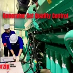
Enerzip performs and records a pre-delivery operational test on every completed generator set.
The operational test record identifies:
- Generator-set identification number
- Test date
- Test operator
- Starting sequence
- Engine speed
- Output voltage
- Output frequency
- Phase sequence
- Oil pressure
- Coolant temperature
- Battery charging voltage
- Controller indication
- Manual start
- Manual stop
- Emergency stop
- Vibration condition
- Mechanical noise
- Fuel leakage
- Oil leakage
- Coolant leakage
- Exhaust leakage
The test operator sets voltage, frequency and controller parameters to the approved order configuration.
The responsible person reviews the operational test record before final release.
16. Load-Bank Test
The approved inspection and test plan defines the load-bank test scope, load points, duration and acceptance limits.
The load-test report records:
- Generator-set identification number
- Load-bank identification number
- Test date
- Test operator
- Active load in kW
- Line voltage
- Phase current
- Frequency
- Engine speed
- Oil pressure
- Coolant temperature
- Battery voltage
- Duration at each load point
- Vibration or noise defect
- Fuel, oil or coolant leakage
- Alarm or shutdown event
A resistive load bank applies active power at a power factor close to 1. A resistive test verifies operation under kW load. It does not verify the complete kVA rating at a power factor of 0.8.
A reactive or combined load-bank report also records:
- Apparent power in kVA
- Reactive power in kVAr
- Power factor
- Alternator current under reactive load
Extended full-load, reactive-load and transient tests are performed only when listed in the approved inspection and test plan.
17. Transient Test
The approved transient-test procedure states:
- Initial load
- Applied load step
- Rejected load step
- Voltage-deviation limit
- Frequency-deviation limit
- Recovery-time limit
- Number of test cycles
- Measuring equipment
- Data-recording method
- Acceptance criterion
Enerzip states compliance with an ISO 8528 G1, G2 or G3 performance class only after completing the applicable ISO load steps, measurements and acceptance limits.
A customer-defined load step is recorded as a project-specific test unless it meets the applicable ISO performance-class requirements.
18. Alarm and Shutdown Test
The alarm and shutdown test record verifies the functions listed in the approved controller configuration.
These functions consist of:
- Emergency stop
- Low oil pressure
- High coolant temperature
- Overspeed
- Under-voltage
- Over-voltage
- Under-frequency
- Over-frequency
- Start failure
- Charging failure
- Low fuel level
- Circuit-breaker trip
- Common alarm
- Remote start
- Remote stop
- ATS start signal
- Communication alarm
The test operator uses controlled signal simulation for a fault condition that would damage the engine or alternator.
19. Additional Project Tests
The approved inspection and test plan identifies every project-specific test.
Project-specific tests cover the following systems when included in the contract:
Gas Generator System
- Gas-train leak test
- Gas-pressure check
- Shutoff-valve operation
- Ignition system
- Air-fuel control
- Engine-control communication
- Exhaust-temperature monitoring
- Emergency gas shutoff
ATS and Paralleling System
- Utility-failure simulation
- Generator start
- Source-available signal
- Transfer sequence
- Return sequence
- Breaker interlocks
- Synchronizing
- Active-load sharing
- Reactive-load sharing
- Generator sequencing
- Load shedding
- Alarm signals
- Communication signals
Medium-Voltage System
- Insulation resistance
- Phase sequence
- Earthing arrangement
- Instrument-transformer configuration
- Protection-relay settings
- Circuit-breaker operation
- Interlocks
- Secondary-injection testing
- Interface signals
Qualified personnel perform medium-voltage tests with equipment rated for the system voltage.
20. Inspection and Test Equipment Control
Enerzip identifies and controls the measuring and test equipment used for product acceptance.
The equipment register records:
- Equipment description
- Equipment identification number
- Calibration or verification status
- Validity date
- Responsible person
The inspection or test report identifies the measuring equipment used for contractual acceptance.
Equipment with expired, damaged or unconfirmed calibration or verification status is not used for product-acceptance measurements.
21. Non-Conformity Control
Enerzip records every item that fails to meet the approved configuration, drawing, production instruction or inspection criterion.
The non-conformity record identifies:
- Affected equipment
- Non-conforming item
- Requirement not met
- Required correction
- Responsible person
- Reinspection or retest result
- Closure status
Correction consists of the action required by the recorded defect, including mechanical adjustment, fastener correction, component replacement, wiring correction, parameter correction, leak repair, paint repair or repeated testing.
The inspector repeats the affected inspection or test after correction.
A required non-conformity is closed before final shipment approval.
22. Final Inspection and Shipment Release
Every completed generator set and electrical panel receives a final inspection before shipment.
The final release record confirms:
- Equipment identification
- Approved configuration
- Completion of production inspections
- Completion of the operational test
- Completion of tests listed in the inspection and test plan
- Closure of required non-conformities
- Nameplate and serial-number records
- Accessories
- Spare parts
- Manuals
- Drawings
- Packing list
- Surface and paint condition
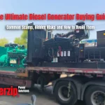
- Packaging
- Transport protection
- Shipment photographs
The responsible person signs the final release record.
Equipment without a completed final release record is not authorized for shipment.
23. Factory Acceptance Test
A customer-witnessed factory acceptance test is performed only when stated in the contract.
The approved FAT procedure defines:
- Equipment covered
- Test sequence
- Load stages
- Test duration
- Recorded parameters
- Acceptance limits
- Witness points
- Hold points
- Required documents
- Non-conformity treatment
- Report format
- Approval responsibility
The contract defines remote witnessing, third-party inspection, schedule, factory access and cost.
24. Large Standby Power-System Integration
A large standby power system consists of the equipment identified in the approved single-line diagram.
The system includes the following items when stated in the contract:
- Generator sets
- ATS equipment
- Paralleling controls
- Power-distribution switchboards
- Transformers
- UPS equipment
- UPS battery systems
- Communication and supervisory interfaces
Enerzip manufactures the generator systems and the power-distribution and control equipment included in its supply scope.
Approved external manufacturers supply the UPS equipment, UPS batteries and large transformers.
Enerzip’s electrical engineers review the interfaces between externally manufactured equipment and Enerzip-manufactured equipment.
The approved interface record covers:
- System voltage
- System frequency
- Generator rating
- UPS input demand
- UPS battery-recharge demand
- Transformer capacity
- Transformer ratio
- Transformer impedance
- Transformer energization current
- Short-circuit requirement
- Circuit-breaker rating
- Protection settings
- Earthing
- Cable interfaces
- ATS sequence
- Breaker interlocks
- Paralleling logic
- Load priority
- Load shedding
- UPS bypass interface
- Remote signals
- Communication protocol
The contract identifies the party responsible for calculations and system studies.
25. Supply and Warranty Responsibility
Customer-Supplied Equipment
Equipment purchased directly by the customer from a nominated supplier remains under that supplier’s product warranty.
Enerzip performs only the technical review, visual inspection, document review, interface coordination or witnessed testing stated in its contract.
Enerzip’s inspection does not transfer responsibility for the external manufacturer’s design, manufacturing defects, certification, spare parts or product warranty to Enerzip.
Customer-Nominated Equipment Procured by Enerzip
The contract states the responsibility for equipment from a customer-nominated manufacturer procured by Enerzip.
Enerzip:
- Verifies the ordered model and documented specification
- Coordinates the equipment interfaces within its supply scope
- Transfers the original-manufacturer warranty in accordance with the manufacturer’s terms
- Assists with valid warranty claims
- Remains responsible for procurement errors, wiring, assembly and integration work performed by Enerzip
Complete System Supplied by Enerzip
When the contract assigns the complete standby power system to Enerzip, Enerzip assumes the quality-control, interface-coordination, system-testing and warranty-management responsibilities stated in the contract.
For third-party UPS systems, battery systems and transformers included in the Enerzip contract, Enerzip:
- Confirms the selected equipment against the approved design
- Reviews the technical data
- Reviews certificates and factory test documents
- Coordinates electrical and control interfaces
- Includes the equipment in the approved inspection and test plan
- Coordinates valid original-manufacturer warranty claims
- Acts as the customer’s contractual contact within the agreed warranty scope
The external manufacturer remains responsible for the internal design and manufacturing warranty of its equipment. Enerzip remains responsible for the system-integration and contractual work completed by Enerzip.
26. Delivery Records
The contract identifies the required delivery records.
The delivery file contains the specified documents from the following list:
- Technical data sheet
- Approved technical configuration
- General arrangement drawing
- Engine data
- Alternator data
- Controller data
- Nameplate photographs
- Serial-number record
- Base-frame inspection record
- Fuel-tank leak-test record
- Enclosure inspection record
- Electrical-panel inspection record
- Pre-start inspection record
- Operational-test record
- Load-test report
- Electrical drawings
- Single-line diagram
- Alarm and shutdown list
- ATS or paralleling sequence
- Measuring-equipment record
- Non-conformity record
- Final release record
- Operation and maintenance manual
- Packing list
- Warranty terms
- Shipment photographs
- Certificates stated in the contract
A factory test report applies only to the equipment identified in that report. It does not replace a product certificate, component certificate or management-system certificate.
27. Standards
The technical agreement identifies the standards applicable to the order.
Referenced generator-set standards consist of:
- ISO 8528-1:2018 — Application, ratings and performance
- ISO 8528-5:2025 — Generating-set design and performance
- ISO 8528-6:2023 — Test methods
- ISO 8528-9:2017 — Measurement and evaluation of mechanical vibrations
- ISO 8528-10:2022 — Measurement of airborne noise
- ISO 8528-13:2026 — Safety requirements
The technical agreement identifies the applicable IEC or other standards for electrical panels and power-distribution equipment.
Referenced electrical-panel standards, when specified in the technical agreement, consist of:
* IEC 61439-1:2020 — General rules for low-voltage switchgear and controlgear assemblies
* IEC 61439-2:2020 — Power switchgear and controlgear assemblies
28. Factory Testing and Site Commissioning
Factory testing covers the equipment under factory conditions.
Site commissioning covers the installed system and the items assigned in the contract:
- Fuel supply
- Ventilation
- Exhaust back pressure
- Power cables
- Earthing
- ATS equipment
- Switchgear
- Transformers
- UPS equipment
- UPS battery systems
- Remote signals
- Paralleling interfaces
- Actual site loads
The approved design, equipment data, installation condition and commissioning results determine final system performance.
Frequently Asked Questions
Does Enerzip test every completed generator set?
Yes. Enerzip performs and records a pre-delivery operational test on every completed generator set.
Does Enerzip leak test every fuel tank it manufactures?
Yes. Every Enerzip-manufactured fuel tank receives a leak test. A failed tank is repaired and retested before release.
Does every generator set receive the same load test?
No. The approved inspection and test plan states the load points, duration and acceptance limits for each order.
Does a resistive load test verify the rated kVA?
No. A resistive load test verifies active power in kW. Verification at a specified kVA and power factor requires a reactive or combined load bank.
Does Enerzip perform every test in ISO 8528 on every generator set?
No. Enerzip performs the tests listed in the approved inspection and test plan. The plan identifies the applicable standard, method and acceptance criterion.
Can the customer witness the factory test?
Yes. The contract and approved FAT procedure define the test, witness points, acceptance criteria, schedule and cost.
What happens after an inspection failure?
Enerzip records the non-conformity, completes the correction, repeats the affected inspection or test and closes the record before shipment approval.
Who provides the warranty for customer-supplied UPS or transformer equipment?
The supplier contracted directly by the customer provides the product warranty. Enerzip’s responsibility is limited to the technical review, inspection and interface work stated in the Enerzip contract.
Who manages the warranty for a complete system supplied by Enerzip?
Enerzip manages the contractual warranty scope and coordinates the original-manufacturer warranty for third-party UPS, battery and transformer equipment included in the Enerzip contract.
Does factory testing replace site commissioning?
No. Factory testing covers factory conditions. Site commissioning verifies the installed fuel, ventilation, exhaust, cable, earthing, switchgear, UPS, transformer, control and load interfaces.
Request an Inspection and Test Plan
Submit the following project data:
- Prime and standby power
- Voltage
- Frequency
- Power factor
- Fuel type
- Application
- Operating profile
- Ambient temperature
- Installation altitude
- Enclosure type
- ATS requirements
- Paralleling requirements
- Transformer interface
- UPS interface
- Applicable standards
- Required tests
- Required documents
- Customer or third-party witness requirements
Enerzip states the inspection, testing, documentation and responsibility scope in the technical offer or contract.
Contact the Appropriate Department
For generator testing, inspection procedures, FAT requirements and technical documents:
Technical Department
technical@enerzip.com
For large standby power projects, system integration, UPS and transformer interfaces, paralleling systems and project engineering:
Projects Department
projects@enerzip.com
For warranty claims, technical faults, replacement parts coordination and after-sales quality matters:
Service Department
service@enerzip.com