Reviewed by: Enerzip Power Technology (Weifang) Co., Ltd. – Applications & Integration Team
Last updated: 22-Dec-2025
Update policy: This guide is reviewed when generator rating definitions, common control practices (ATS/paralleling), or typical project testing scopes (FAT/SAT) materially change.
Scope: Industrial generator system sizing workflow (diesel / natural gas / biogas), focused on standby power and project-grade integration.
About the reviewing team
Enerzip Applications & Integration Team supports EPC contractors, distributors, and industrial users on sizing, controls scope (ATS/load shedding/paralleling),
and acceptance testing plans (FAT/SAT) for standby generator systems across data centers, hospitals, manufacturing, utilities, mining, and remote sites.
Keywords: industrial backup generator • industrial standby generator • standby generator for industrial loads • backup genset • kW vs kVA • ISO 8528 ratings (ESP/PRP/COP) • load profile • motor starting • step load • site derating • ATS • paralleling • FAT/SAT
Why most standby generator sizing fails in real projects
Sizing an industrial backup generator is not “add up the kW and buy a bigger kVA.” Most failures show up during the first real blackout test or the first unplanned outage—when the industrial backup power system must carry real loads with real starting behavior, real ATS timing, and real site constraints.
Common failure symptoms during the “moment of truth”:
- Voltage dips cause PLCs, drives, or contactors to drop out
- Frequency dips trigger UPS alarms or nuisance trips
- Large motors fail to re-accelerate after transfer
- High ambient temperature pushes coolant temperature beyond limits
- The actual site load differs from RFQ assumptions (missing loads, wrong start method, wrong duty)
Nearly every failure traces back to one of these gaps:
- Load profile is incomplete (what runs, when it runs, and how it starts)
- Starting and step-load behavior wasn’t validated (motors, compressors, VFDs, UPS/rectifiers)
- Site conditions were not applied (temperature, altitude, enclosure airflow, fuel quality)
- Transfer & control scope wasn’t defined (ATS timing, load shedding, start sequence, paralleling logic)
This guide provides a repeatable workflow to turn “power requirements” into an RFQ-ready industrial standby generator configuration—reducing downtime risk and avoiding expensive oversizing.
1) Define the duty: what “backup” really means
Before calculation, define how the industrial backup generator will actually run. In industrial projects, “backup” can mean very different operating realities:
- Emergency standby for rare utility outages (short runtime, variable load)
- Frequent backup / poor grid (regular operation, longer runtime)
- Continuous / baseload (long-duration, near-constant load)
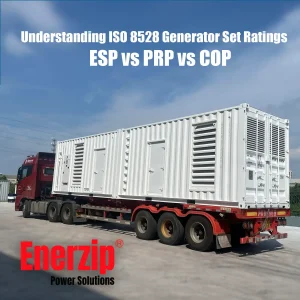
Ratings are often discussed in the market using ISO 8528 terminology (or equivalent rating language in supplier datasheets). Rating definitions may vary by manufacturer interpretation; confirm the stated rating basis in the datasheet and the intended test scope (FAT/SAT).
- ESP (Emergency Standby Power): outages only, variable load, limited annual hours
- PRP (Prime Rated Power): utility absent/unreliable; variable load
- COP (Continuous-type operation): constant or near-constant load over long duration
Why it matters: A standby generator for industrial loads can be “big enough” in kVA yet still be the wrong choice if the rating category does not match your duty cycle. Duty drives fuel strategy, maintenance planning, and how conservative your redundancy and margin should be.
RFQ prompts:
- Expected running hours per year (and longest continuous run)
- Is the backup genset emergency-only or frequent operation?
- Any sustained high-load periods?
- Availability target: single set / N+1 / 2N?
2) kW vs kVA: the most common sizing mistake
Many sizing mistakes happen because people treat kW and kVA as interchangeable. For an industrial backup generator, both matter.
kW is real power that does useful work. kVA is apparent power the alternator must supply, including reactive demand. Power factor (PF) connects them:
kW = kVA × PF
kVA = kW / PF
Many industrial generator sets are referenced at PF 0.8 (common in nameplates). That means:
- 1000 kVA at PF 0.8 → 800 kW
Why kVA matters: motor content, PF variation during transients, and UPS/rectifier behavior can push kVA demand far above steady running kW. A correctly specified industrial standby generator must handle the worst transient event, not just the steady total. For general reference on generating-set design and performance criteria under load, readers may also review the ISO 8528-5 performance standard.
3) RFQ-ready sizing workflow
This is a practical workflow that EPC teams and plant engineers can use to size an industrial backup power system with fewer surprises.
Step 1 — Build a load list
Your load list must include how loads start, not only running power. Minimum fields:
- Load name / tag
- Load type (motor, VFD motor, compressor, UPS, lighting, heater, transformer, etc.)
- Running kW or running kVA
- PF (if known)
- Starting method (DOL, star-delta, soft starter, VFD)
- Starting current or starting kVA (for motors)
- Duty (always-on, intermittent, emergency-only)
- Priority (must-run / delay-start / shedable)
Step 2 — Normalize to a common basis (kW, kVA, A)
- If you have kW and PF: kVA = kW / PF
- If you have 3-phase current: kVA = (√3 × V × A) / 1000 (V is line-to-line voltage for 3-phase systems)
Step 3 — Separate “running totals” from “worst-case event”
- Steady running load (kW/kVA once stable)
- Worst-case start/step event (the moment that stresses the backup genset most)
Step 4 — Define a start sequence
Staged starts reduce required size and improve stability—often the fastest way to make an industrial backup generator behave better without buying a larger alternator.
- ATS transfer occurs → essential controls/lighting stabilize
- Start the largest must-run motor alone (if possible)
- Start secondary motor groups with time delays
- Enable non-essential loads last
Step 5 — Apply site derating
- High ambient temperature (40–50°C)
- Altitude
- Enclosure / container airflow restrictions
- Fuel type and fuel quality variability (especially for gas/biogas)
- Accessory loads (fans, heaters, chargers, pumps)
Step 6 — Add margin intelligently
- 10–15% when load data is solid and starts are staged
- 15–25% when loads are uncertain, expansion is likely, or environment is harsh
- If the main risk is transient, consider controls/paralleling before oversizing the industrial standby generator
Step 7 — Validate transient performance
- Voltage dip tolerance of PLC/VFD/controls
- Frequency recovery (turbo engines + big steps need attention)
- Motor re-acceleration after transfer
- UPS/rectifier compatibility (step load and harmonics)
Enerzip Field Note 1 (RFQ clarity): In EPC RFQs, the most common missing inputs are:
(1) the largest motor start method (DOL / star-delta / VFD) and whether starts are staged,
(2) UPS/rectifier load pick-up behavior (instant step vs managed ramp),
(3) the site environment (high ambient + enclosure airflow path).
Practical verification item: If your PLC/control loads require tight stability, state an acceptance target such as “voltage dip < 15% for ≤ 1–2 seconds” during the worst start event, and confirm it during FAT/SAT.
4) Motor starting: the #1 sizing surprise
Motor starting is usually the #1 reason an industrial backup generator is oversized—or still fails even after oversizing. For general reference on industrial and commercial motor-starting analysis, readers may also review IEEE 3002.7 motor-starting studies.
Typical ranges (confirm with motor datasheets):
- DOL (Direct-On-Line): often 5–7× running current (highest dip risk)
- Star-delta: commonly 2–3× running current (transition creates a step)
- Soft starter: reduces peak current; reactive demand may still be significant
- VFD: often best for generator compatibility when configured correctly; may introduce harmonics
Re-acceleration after transfer
After ATS transfer, motors may slow down and then demand high current to re-accelerate—causing a second dip. A project-grade standby generator system typically includes staged restart, interlocks, and time delays to prevent “all motors restart at once.”
5) Step load & transient response
Two units with the same kVA can behave very differently under sudden load steps. For an industrial standby generator, transient response depends on:
- Governor behavior and tuning
- AVR excitation capability
- Rotating inertia
- Turbo response and fuel system
- Control strategy (sequencing, shedding, paralleling)
Practical rule: Do not design a standby generator for industrial loads assuming “everything starts at once” unless you have validated transient capability and your loads can tolerate dips.
6) Worked example
Illustrative example only. Final sizing must be verified against motor datasheets, UPS behavior, and site conditions.
Assumptions (example): 400V, 3-phase, 50Hz; average PF 0.85.
| Load | Type | Running kW | PF | Running kVA | Start method | Typical start kVA | Notes |
|---|---|---|---|---|---|---|---|
| Process Pump #1 | Motor | 55 | 0.85 | 64.7 | DOL | ~6× = 388 | Start alone |
| Process Pump #2 | Motor | 55 | 0.85 | 64.7 | DOL | ~388 | Stagger start |
| Air Compressor | Motor | 75 | 0.85 | 88.2 | Star-delta | ~2.5× = 221 | Lower inrush |
| Cooling Fans (group) | Motors | 30 | 0.85 | 35.3 | DOL | ~4× = 141 | Group control |
| Lighting | Mixed | 20 | 0.95 | 21.1 | — | — | LED drivers |
| PLC/Controls | Electronic | 15 | 0.95 | 15.8 | — | — | Sensitive loads |
| UPS (IT + control) | UPS | 40 | 0.90 | 44.4 | — | Step load | Confirm ramp vs step |
| Fire Pump | Motor | 90 | 0.85 | 105.9 | DOL | ~6× = 635 | Must run |
Running total: about 390 kW (≈ 451 kVA). If you size only by running totals, you may choose 500–630 kVA and still fail on the worst-case start event. In many sites, the correct answer is not simply “bigger,” but a better start sequence and clearer control scope for the industrial backup generator.
Two configuration directions:
- Option A — Single set + strong sequencing: often lands in the 800–1000 kVA class (final depends on dip tolerance, derating, and ATS/control scope).
- Option B — Parallel sets: e.g., 2 × 500–630 kVA (N+1 optional) for stronger step-load behavior and higher availability.
Enerzip Field Note 2 (hot sites): In hot regions, more failures come from cooling margin and airflow restrictions than from steady kVA.
Practical verification item: During commissioning (or SAT), record radiator inlet/outlet air temperatures and stable coolant temperature under representative load.
If the enclosure/container airflow causes recirculation, the system may overheat even when nameplate kVA looks sufficient.
Acceptance targets
These targets make the document read like a project file and help vendors quote consistently. Final targets must match your actual load tolerance (PLC/VFD/UPS).
- Voltage dip: ≤ 15% for ≤ 1–2 seconds during the worst motor start event (typical for PLC/control-heavy loads)
- Frequency dip: ≤ 10%, with recovery within ≤ 5 seconds after the largest step event
- Maximum single step load: define whether UPS/rectifier is “instant step” or “managed ramp” (e.g., 0–100% in 3–10 seconds)
- ATS strategy: open transition vs closed transition, transfer delay, re-transfer delay, and staged restart logic
7) Site derating: temperature, altitude, enclosure, fuel
- Temperature: high ambient reduces usable output and cooling headroom for the standby generator system.
- Altitude: thinner air reduces engine output.
- Enclosures/containers: airflow restrictions can reduce usable capacity—especially in 40–50°C sites.
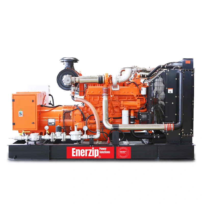
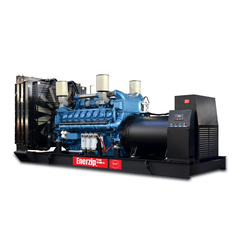
- Fuel quality: diesel vs natural gas vs biogas affects transient behavior and design requirements (gas composition stability matters).
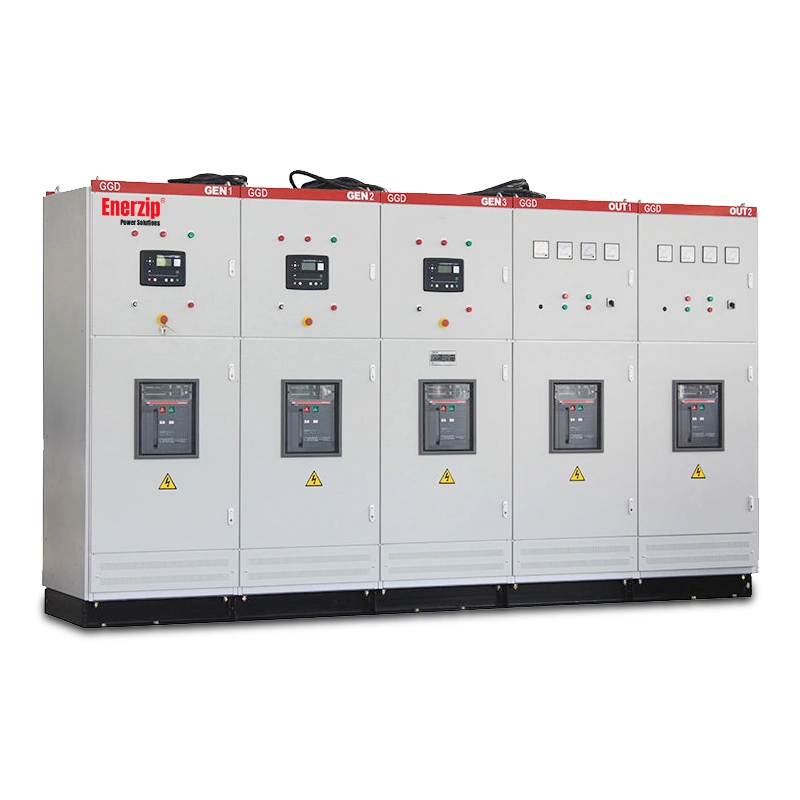
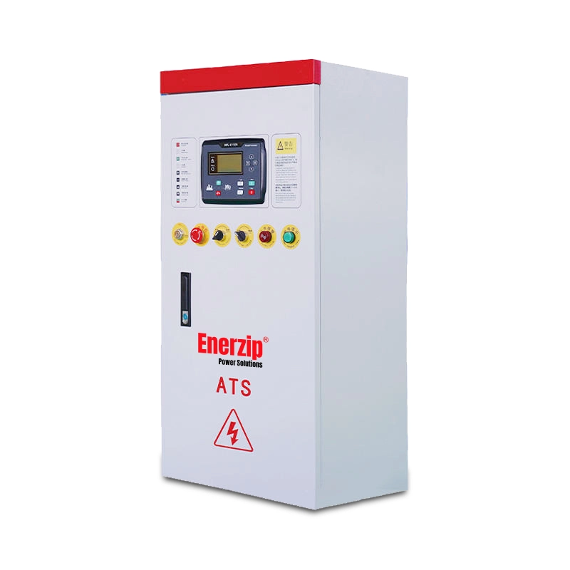
8) ATS, load shedding, and control scope
ATS defines the “moment of truth”
ATS transfer settings influence load pick-up timing and whether loads return all at once. Many “generator problems” are actually ATS + restart behavior issues, not a nameplate issue of the industrial backup generator.
Load shedding reduces size and improves stability
Split loads into tiers to make the standby generator for industrial loads stable and cost-effective:
- Tier 1 (must-run): safety systems, controls, critical operations
- Tier 2 (delay-start): pumps, compressors, staged HVAC
- Tier 3 (shedable): non-critical loads
9) Paralleling: when one big unit is not safer
When step-load or availability is the primary risk, two smaller sets in parallel can outperform one oversized industrial standby generator. Paralleling can improve step-load acceptance, enable maintenance without total shutdown, and provide modular expansion for future loads.
Enerzip Field Note 3 (architecture choice): “One big genset” is not always the safest option.
Practical verification item: If your worst-case event is a large motor re-start after ATS transfer, a parallel architecture may achieve smaller voltage dip and faster recovery than a single oversized unit—provided synchronizing logic and staged load pick-up are specified and tested.
10) Margin strategy that feels like engineering
- 10–15% for solid data + staged starts + known environment
- 15–25% for uncertain loads, expansion plans, harsh ambient
- For harsh transients, improve controls/architecture before simply upsizing the industrial backup generator
11) RFQ checklist + load list template
Load & operation
- Full load list: running kW/kVA, PF, duty, priority
- Largest motor: kW/HP, start method, starting current/kVA
- Start sequence plan (staged starts, interlocks, delays)
- UPS/rectifier notes: step-load behavior, harmonics limits
- Target duty: emergency-only vs frequent operation for the backup genset
Site conditions
- Voltage / frequency / phases / grounding
- Ambient temperature range and altitude
- Indoor/outdoor, canopy/container, airflow constraints
- Fuel type and constraints (gas/biogas quality window if applicable)
Controls & architecture
- ATS rating and transfer settings
- Load shedding tiers and logic
- Remote monitoring and communication needs
- Paralleling requirement or future expansion plan
Load List Template
- Load Tag / Name
- Load Type (Motor / VFD Motor / UPS / Lighting / Heater / Other)
- Quantity
- Voltage (V), Phase (1P/3P), Frequency (50/60Hz)
- Running kW (each), Running PF, Running kVA (calc), Running Current (A)
- Start Method (DOL / Star-Delta / Soft Starter / VFD)
- Starting Current (A) or Starting kVA, Start Duration (s)
- Duty (Continuous / Intermittent / Emergency-only)
- Priority (Must-run / Delay-start / Shedable)
- Notes (re-acceleration risk, harmonics, special constraints)
12) What to put on nameplate / datasheet
To make your RFQ “project-grade,” specify what must appear on the nameplate and datasheet. This prevents misunderstanding and improves the quality of standby generator proposals.
- Electrical basics: rated voltage, frequency, phase/wiring, grounding approach (as required)
- PF basis: state the PF used for rating (commonly 0.8 unless otherwise specified)
- Rating statement: ESP/PRP/COP category + kVA and kW shown together under the stated PF
- Site reference: ambient temperature and altitude for which rating is valid
- Alternator: insulation class, IP, AVR, anti-condensation heater (if needed)
- Engine & fuel: diesel / natural gas / biogas; governing type; fuel quality window for gas/biogas sites
- Controls scope: controller model, protections, ATS interface, paralleling/synchronizing scope, remote monitoring protocol
13) Acceptance testing: FAT/SAT essentials
“Rated power” is not proven until the standby generator system is tested under conditions that reflect real site constraints and control scope.
FAT (Factory Acceptance Test)
- Visual/build inspection: wiring, labeling, workmanship, leak check
- Insulation/verification checks for alternator and key circuits
- Protection checks: over/under V & Hz, overspeed, emergency stop, alarms
- Functional checks: controller logic, sensors, breakers, ATS interface (as applicable)
- Load test (when required): staged steps to evaluate voltage/frequency dip and recovery
SAT (Site Acceptance Test / Commissioning)
- Site integration: grounding, cable sizing, ATS settings, ventilation path
- Transfer test: utility-to-generator transfer, re-transfer behavior
- Start sequence validation: staged motor starts, delay logic, shedding logic
- Worst-case event test: largest motor start after transfer + critical load pickup
- Thermal verification: validate cooling margin in representative ambient conditions
FAQ: industrial backup generator sizing
1) Should I size by kW or kVA?
Use both. kW reflects real demand; kVA reflects what the alternator must deliver including reactive power—especially during motor starting and transients for an industrial backup generator.
2) Which rating should I specify: ESP or PRP?
Match rating to duty cycle. If the standby generator runs frequently or supports weak-grid operation, PRP-type selection is usually more appropriate than emergency-only assumptions.
3) Why does a genset trip during motor start even if kW is below rating?
Because motor starting is primarily a transient current/kVA event. Voltage/frequency dips or overcurrent protection may trigger long before steady kW reaches nameplate.
4) How much margin is enough?
Typically 10–15% for defined loads with staged starts; 15–25% when loads or site conditions are uncertain. For harsh transients, improve controls/paralleling instead of only increasing nameplate size.
5) Does a silent enclosure affect sizing?
Yes. Enclosures can restrict airflow and reduce usable output in high ambient conditions; treat ventilation as part of the standby generator system design.
6) Is paralleling always necessary?
No, but it can significantly improve step-load behavior and availability for critical sites. It is often justified when downtime cost is high or load steps are large.
Next step
If you share your load list (Excel), site temperature/altitude, duty intent (standby vs frequent operation), and ATS/control requirements, Enerzip can convert it into an RFQ-ready recommendation for your industrial backup power system:
- Suggested sizing range (kVA/kW) with assumptions stated
- Start sequence and load shedding tiers
- Whether paralleling is appropriate and how to structure it
- FAT/SAT scope aligned with your acceptance targets
Related resources
- Generator Specification Checklist for EPC Projects
- Genset FAT Testing & Inspection Steps + Warranty Support
- Diesel Generator Sets
- Natural Gas Generator Sets
- Biogas Generator Sets
- Automatic Transfer Switches (ATS)
Note: This article provides an engineering workflow guide. Final sizing should be validated with motor datasheets, UPS manufacturer notes, site environment constraints, and an acceptance testing plan (FAT/SAT).