Genset FAT/SAT testing is the practical way to prove a standby generator system will survive real outage events—utility loss, ATS transfer, step loads, motor re-acceleration, and high-ambient operation—before those events become costly commissioning rework or downtime.
About the reviewing team
Enerzip Applications & Integration Team supports EPC contractors, distributors, and industrial users by translating load profiles, duty cycles, and site constraints into actionable generator configurations. We typically validate assumptions through FAT/SAT planning, staged load pick-up logic, and site airflow/cooling checks—because most real project failures happen at transfer, motor start, step load, or high-ambient operation.
Why FAT/SAT is where reliability becomes real
In industrial standby power, most failures do not appear at “rated kW.” They appear during short, stressful moments: transfer, staged load pick-up, the largest motor start, UPS/rectifier step load, and thermal stability in real airflow conditions. A unit can pass a steady load bank run and still fail at the site’s “moment of truth” if the RFQ never defined the events—or if testing verified only steady-state behavior. For general reference on acceptance testing specifications for electrical power equipment and systems, readers may also review ANSI/NETA ATS.
- Procurement clarity: suppliers quote the same control scope and test method, not assumptions.
- Commissioning speed: fewer “redo cycles” caused by missing sequences, missing settings, or missing airflow planning.
- Dispute prevention: a “pass” means passing the events that matter, not only a steady load number.
Enerzip Field Note: Post-delivery disputes rarely start with “kW is insufficient.” They start with an undefined event—ATS transfer timing, the largest motor re-acceleration after transfer, UPS/rectifier pick-up behavior, or enclosure airflow path at high ambient. A supplier may pass a steady load test but fail on site because the acceptance condition was never written.
Practical fix: put acceptance targets into the RFQ and tie them to FAT/SAT. Then require a compliance matrix and a test-data package (timestamps + min V/Hz + recovery time + thermal logs).
Define acceptance targets before you test
If you do not define targets, FAT/SAT becomes a “check-the-box demonstration,” and everyone walks away with a different definition of success. For general reference on generating-set test methods, readers may also review ISO 8528-6. You do not need to quote standard text. You only need to state what your loads can tolerate and what the site must achieve.
1) Use event-based targets
Targets must match real equipment tolerance (PLC, UPS, VFD, medical devices, server power supplies). The numbers below are common practical starting points for sensitive-load sites. Your project must confirm them against actual load tolerance.
- Motor-start event (after transfer): Voltage dip (VLL) ≤ 15% for ≤ 2 seconds.
- Largest step load event: Frequency dip ≤ 10% with recovery to ≥ 98% nominal within ≤ 5 seconds.
- Transfer behavior: transfer complete within 10–15 seconds (utility loss detect → load on generator), with generator V/Hz stable before breaker close.
- Thermal stability: no thermal alarms/derate during a 2–4 hour representative run at 75% rated kW (or expected site continuous load, whichever is higher).
2) Make targets measurable
Write targets so they can be measured using controller trends, external power-quality meters, and temperature logs. A measurable statement looks like: “Minimum line-to-line voltage during the largest motor start shall not drop below 85% nominal for longer than 2 seconds.”
3) Tie targets to test steps
Targets without test steps become arguments. Targets with test steps become evidence. Each target should map to:
- Which event triggers the target (ATS transfer / largest motor start / UPS recharge / thermal run / paralleling step).
- Which instrumentation is used (controller trend export, external PQ meter, temp probes).
- What data must be recorded (min VLL, min Hz, dip duration, recovery time, step size in kW/kVA, timestamps).
Event-based acceptance matrix
This table is designed for EPC RFQs and commissioning. It forces clarity: what success looks like, how you test it, and what evidence you expect.
| Event | Acceptance Target (Project to confirm) | How to Test (FAT / SAT) | Instrumentation / Evidence | Vendor Response (Comply / Deviate) | Notes |
|---|---|---|---|---|---|
| ATS Transfer Timing | Transfer complete within 10–15 seconds (utility loss detect → load on generator). Generator V/Hz stable before breaker close: ≥95% VLL and ≥98% Hz for ≥2 seconds. |
SAT: utility loss simulation; record timestamps for loss detect, start, ready, breaker close, ATS transfer complete; repeat 3 cycles. | ATS event log + controller event/trend timestamps + timestamp sheet. | Comply / Deviate | Include breaker close permissives; state open-transition vs closed-transition; define re-transfer delay and cooldown/unload behavior. |
| Largest Motor Start After Transfer | Voltage dip (VLL) ≤ 15% for ≤ 2s. Frequency dip ≤ 10% with recovery to ≥ 98% nominal within ≤ 5s. No nuisance trip of PLC/VFD controls. |
FAT (if feasible): staged step load equivalent. SAT: start actual largest motor 1–3 min after transfer while Tier-1 loads are on. |
External PQ meter + controller VLL/Hz/kW/kVA trend export + motor start method proof. | Comply / Deviate | State start method: DOL / Star-Delta / Soft Starter / VFD; provide motor kW/HP, accel time, inrush/starting kVA; require staged restart schedule to avoid “all motors restart together”. |
| UPS Step / Recharge (if used) | No UPS bypass/rectifier trip; recharge must be controlled ramp: ≤ 10% of UPS rated kW per minute (or ≤ 20%/min if UPS vendor allows). During recharge enable: voltage dip ≤ 10% for ≤ 1s; frequency recovery ≤ 5s. |
SAT: run UPS on battery briefly (or simulate), then enable rectifier/recharge; test (1) normal ramp, (2) worst-case permitted ramp; record genset response. | UPS logs + genset kW/kVA trend + PQ meter snapshot (min VLL/min Hz). | Comply / Deviate | Provide UPS compatibility note; state recharge settings used in test; confirm step vs ramp behavior; record THDi if available. |
| Thermal Run (High Ambient / Enclosure) | No thermal alarms/derate during 2–4 hours run at 75% rated kW (or expected continuous site load, whichever is higher). Coolant temp stabilizes (no continuous rise after 60–90 min). Enclosure/room temp stable (no recirculation indication). |
SAT: representative run 2–4 hours; record ambient + coolant + radiator inlet/outlet air + enclosure temp every 15–30 min; verify airflow path/duct pressure drop/recirculation control. | Coolant/air/enclosure temp log + controller trend export + photos of airflow path and louvers/ducting. | Comply / Deviate | Confirm airflow direction; document ducting and pressure drop; note accessories affecting cooling (canopy, louvers, aftertreatment); hot-site failures are usually airflow/recirculation, not kVA. |
| Paralleling (if applicable) | Sync and close within 10–20 seconds after start permissive. Stable kW sharing within ±10% of proportional share at steady load. No hunting after a 10–20% system step load. Optional N+1 proof: with one unit offline, remaining units carry Tier-1 load without blackout. |
FAT + SAT: verify sync permissives and breaker logic; SAT step loads 10–20% and record kW/kVAr sharing trend; optional simulate loss of one unit if required. | Power management controller logs + kW/kVAr sharing trend per unit + system VLL/Hz trend + protection settings list. | Comply / Deviate | Include protection coordination and load-share method (kW/kVAr or PF control); require integration boundary statement (switchgear/controller/CT-PT/interlocks); record breaker close timestamps. |
FAT scope: what to verify at the factory
Factory Acceptance Testing should prove build quality, functional logic, protections, and—when required—the system’s ability to accept staged load steps. FAT is also where you lock down configuration details that are expensive to change on site.
FAT 1 — Visual inspection & build verification
- General assembly: mounting, vibration isolators, fasteners, alignment, labeling.
- Fluids: leaks, hose routing, clamps, fuel lines, coolant hoses, exhaust joints.
- Electrical workmanship: cable dressing, gland sealing, lug torque marks, grounding/bonding points.
- Safety: guards, emergency stop stations, hot-surface warnings, rotating equipment protection.
FAT 2 — Documentation alignment
- Confirm quoted rating basis: kVA + kW shown together, PF basis stated (confirm duty rating category in supplier datasheet).
- Confirm configuration: controller model, breaker type, ATS interface scope, paralleling scope (if any).
- Confirm drawings consistency: SLD, wiring, terminal schedule, I/O list (if required), GA drawings.
FAT 3 — Protection & alarm checks
- Over/under voltage, over/under frequency, overspeed, emergency stop function.
- Low oil pressure, high coolant temperature, fail-to-start, battery charging alarms.
- Breaker trip philosophy and settings list provided (for coordination review).
FAT 4 — Control logic checks
- Start/stop, warm-up, cooldown, alarms, shutdown sequencing.
- ATS interface simulation (as applicable): start signal, generator ready, breaker close permissives.
- Load shedding simulation (if included): underfrequency trigger, staged restoration logic.
- Paralleling logic (if included): sync permissives, load sharing behavior, alarm handling.
Enerzip Field Note (simple deliverable that prevents site failure): If the project depends on staged pick-up, require a time-delay schedule table during FAT (example: “Tier 1 at t=0–5s, Pump Group A at t=30s, HVAC block at t=90s”). This prevents a common SAT failure: “everything picked up together.”
FAT 5 — Load tests (when required): staged steps, not only steady load
If your risk is transient performance (PLC/UPS/VFD sensitivity, motor-start events), a steady load test alone is not enough. Consider staged step tests that resemble your event list:
- Step loads at 25% → 50% → 75% (and 100% if required), recording min VLL/min Hz and recovery time.
- If motors are the risk: simulate an equivalent kVA step, or test with representative motor loads when practical.
- For parallel systems: add steps while verifying kW sharing stability and no hunting.
FAT 6 — Thermal & airflow checks
- Confirm fan direction, radiator airflow direction, alarm thresholds, basic cooling behavior.
- For canopy/container: confirm service access is practical; identify airflow path risks early.
SAT scope: what proves readiness at the site
Site Acceptance Testing proves integration: grounding, cables, ATS settings, ventilation path, and the real behavior of your loads during transfer and restart. SAT is where commissioning either becomes operational reality—or becomes a schedule delay.
SAT 1 — Site readiness checks
- Foundation/plinth: levelness, anchor torque, drainage, vibration isolator condition.
- Grounding/earthing: bonding continuity and system philosophy matches design.
- Cables/terminations: torque verification, phase rotation check, lug and gland integrity.
- Exhaust: routing, backpressure assumptions, safe discharge direction.
- Ventilation: clear inlet/outlet, no short-circuit recirculation path, louvers/ducts installed as designed.
- Fuel readiness: diesel storage/filtration; gas pressure stability; biogas conditioning and condensate management ready.
SAT 2 — ATS transfer & re-transfer behavior
- Simulate utility loss; verify timestamps: loss detect → crank → ready → breaker close → transfer complete.
- Verify “return to utility”: re-transfer delay, cooldown/unload logic, and whether loads surge on re-transfer.
- Confirm neutral switching (if applicable) matches grounding philosophy.
SAT 3 — Staged load pick-up & shedding logic
- Validate staged pick-up schedule with real loads (Tier 1, Tier 2, Tier 3).
- Validate shedding tiers (if used): triggers, delays, restoration sequence.
- Confirm largest motor does not restart simultaneously with other major loads unless intentionally designed.
SAT 4 — Worst-case event test
Pick one realistic worst-case event based on the site load profile:
- Largest motor start after transfer (including re-acceleration behavior), or
- Largest step electronic load (UPS pick-up/recharge behavior), or
- Combined event only if the site realistically allows it.
Enerzip Field Note (site evidence that reduces rework): For high-ambient or enclosure-constrained sites, require a thermal run log: coolant temperature at stable load, radiator inlet/outlet air temperature, and enclosure/room internal temperature. These measurable items help separate “load issues” from “airflow issues.”
SAT 5 — Thermal verification under representative conditions
Thermal failures often appear after 1–3 hours, not during the first 10 minutes. If the project requires long-duration run capability, include a representative-duration run at a realistic load level and ambient window, and record the thermal dataset.
The “event list”: the fastest way to prevent disputes
Put this short event list into your RFQ and require suppliers to respond with a test method and compliance statement for each item.
- Utility loss → ATS transfer complete: timing recorded (10–15s target; confirm).
- Tier-1 staged pick-up: sequence verified; no unstable oscillation.
- Worst-case event: motor start or UPS recharge; verify min VLL/min Hz and recovery time.
- Thermal run: 2–4h representative run; log coolant/air/enclosure temps.
- Paralleling (if applicable): sync, sharing stability, step load behavior, optional unit-loss simulation.
Data logging: what to record so arguments become facts
Many projects “test” but do not record the right data. The result is disputes and repeated troubleshooting. A practical logging package should include:
Electrical stability
- Minimum line-to-line voltage (VLL) and dip duration (seconds).
- Minimum frequency (Hz) and recovery time back to stable band.
- Step size at the moment of dip (kW, kVA, and if possible kVAr/PF).
- Breaker close timestamps and ATS timestamps for transfer events.
Thermal stability
- Coolant temperature trend at stable load (look for stabilization after 60–90 min).
- Radiator inlet/outlet air temperature (or room inlet/outlet if ducted).
- Enclosure/room internal temperature (helps detect recirculation).
- Any derating behavior, alarms, or fan-stage changes.
Controls evidence
- Staged pick-up schedule table (time delays by load tier/group).
- ATS settings: transfer delay, re-transfer delay, cooldown/unload logic.
- Shedding triggers and thresholds (if used).
- Paralleling parameters (if used): sync window, load sharing settings.
Common failures and practical fixes
Failure 1 — PLC/VFD trips during motor start after transfer
Typical root causes: voltage dip too deep, motors restart together, no staged restart, re-acceleration demand underestimated.
Practical fixes: stage motor restarts; start largest motor alone; apply shedding on underfrequency; use soft starter/VFD ramp where appropriate; confirm acceptance targets match real equipment tolerance.
Failure 2 — UPS causes unexpected step load
Typical root causes: UPS recharge not controlled; rectifier behavior not declared; harmonics/kVA demand underestimated.
Practical fixes: require UPS pick-up behavior in writing; configure recharge ramp; stage UPS recharge after critical motors stabilize; verify generator-UPS compatibility notes during procurement.
Failure 3 — Thermal alarms in hot regions despite “rated power”
Typical root causes: airflow recirculation; duct pressure drop too high; canopy/container ventilation not treated as part of system; high ambient + accessories reduce margin.
Practical fixes: redesign airflow path; prevent short-circuit recirculation; record radiator inlet/outlet air temperatures during SAT; confirm accessory loads and fan power assumptions; apply site derating realistically.
Failure 4 — Quotes “pass” FAT but fail SAT
Typical root causes: FAT tested only steady state; SAT readiness incomplete; ATS settings differ from design intent.
Practical fixes: require event-list-aligned FAT steps; finalize ATS parameters before SAT; use commissioning checklist; record evidence logs so changes are traceable.
RFQ-ready FAT/SAT scope
RFQ — Genset FAT/SAT Testing & Commissioning Scope
- Project intent: standby vs frequent backup; annual runtime hours; longest continuous run; uptime target (single / N+1 / 2N).
- Electrical basics: voltage; frequency; phase/wiring; grounding philosophy; PF basis for rating (supplier to state rating basis in datasheet).
- Event list (must be verified): (1) ATS transfer timing, (2) staged pick-up schedule, (3) worst-case load event (largest motor start or UPS step), (4) thermal run under representative airflow constraints, (5) paralleling event (if applicable).
- Acceptance targets (project to confirm): transfer complete 10–15s; motor-start voltage dip ≤15% for ≤2s; largest step-load frequency recovery to ≥98% within ≤5s; UPS recharge ramp ≤10% UPS rated kW/min (or ≤20%/min if UPS vendor allows); thermal run 2–4h @75% rated kW without alarms/derate.
- FAT requirements: visual inspection; wiring verification; protections and alarms; control logic verification; ATS interface simulation; staged load step tests where required by event list.
- SAT requirements: site readiness checklist; transfer and re-transfer tests; staged restart validation; worst-case event test; thermal verification and logs.
- Documentation deliverables: datasheets; SLD; wiring diagrams; GA drawings; settings lists; FAT report; SAT checklist; spares list; O&M manuals; trend exports/log files.
- Supplier response format: compliance matrix (Comply / Deviate / Optional / Not included) + assumptions + exclusions + proposed test method + evidence list.
Annexes: checklists + templates
Annex A — FAT Checklist
- Build inspection: labeling, wiring, leaks, safety guards, grounding points, torque marks.
- Controller checks: start/stop, alarms, shutdowns, cooldown, event logs enabled.
- Protection checks: over/under V & Hz, overspeed, E-stop, sensor alarms.
- ATS interface simulation (if applicable): start signal, ready, breaker close permissives, cooldown logic.
- Staged step-load tests (if required): record min VLL, min Hz, dip duration, recovery time, step size (kW/kVA).
- Paralleling tests (if applicable): sync permissives, close timing, sharing stability, alarms.
Annex B — SAT Checklist
- Site readiness: foundation, grounding, cables/torque, exhaust, ventilation path, fuel readiness.
- ATS tests: utility loss simulation; record transfer timing; verify re-transfer + cooldown behavior.
- Staged pick-up: verify delay schedule and no simultaneous major restarts.
- Worst-case event test: largest motor start or UPS recharge; verify targets and record logs.
- Thermal run: record coolant temp + radiator inlet/outlet air temp + enclosure/room temp every 15–30 minutes (2–4h run).
Annex C — Event Log Template
Copy this into Excel. Keep the first row as headings. The second row is an example entry to show what “complete evidence” looks like—replace with your real test data.
| Event Name | Timestamp | Step Size (kW / kVA) | Min Voltage (VLL) | Voltage Dip (%) | Dip Duration (s) | Min Frequency (Hz) | Recovery Time (s) | Notes |
|---|---|---|---|---|---|---|---|---|
| ATS Transfer | 2026-02-02 10:15:32 | +180 kW / +225 kVA | 372 V (400V nominal) | 7.0% | 0.6 | 47.8 Hz (50Hz nominal) | 2.4 | Open-transition; transfer complete 12.4s; V/Hz stable before close. |
| Largest Motor Start | 2026-02-02 10:18:10 | +95 kW / +160 kVA | 344 V | 14.0% | 1.8 | 45.6 Hz | 4.6 | Motor start method: soft starter; staged restart applied; no PLC trips. |
| UPS Recharge | 2026-02-02 10:21:05 | +60 kW / +78 kVA | 360 V | 10.0% | 0.9 | 46.9 Hz | 4.2 | Recharge ramp set to 10% UPS rated kW/min; no UPS bypass. |
| Thermal Run (steady) | 2026-02-02 12:30:00 | ~75% rated kW | N/A | N/A | N/A | N/A | N/A | 2.5h run; coolant stabilized; radiator inlet/outlet air temps logged; no alarms/derate. |
FAQ
1) Do I need a load bank test for every project?
Not always. If your risk is simple standby with tolerant loads, a full load bank program may be optional. If your risk is transient performance (sensitive controls, UPS behavior, large motors), staged step tests aligned to the event list are often more valuable than a single steady run.
2) Why does a system pass FAT but fail on site?
Because FAT often validates steady state, while the site fails on ATS timing, restart behavior, UPS recharge, or airflow constraints. Align FAT/SAT to the same event list and record evidence logs.
3) What is the best “acceptance target” to reduce disputes?
The best targets are event-based and measurable: voltage dip depth/duration for the worst motor start, frequency dip and recovery time for the largest step load, and thermal stability under representative airflow constraints. Always confirm targets against real equipment tolerance.
4) How do we avoid “all motors restart together” after transfer?
Write staged restart into the RFQ: define tiers, require a time-delay schedule, and validate it during SAT. If needed, add shedding triggers during recovery.
Next step
If you share (1) your load list (Excel), (2) duty intent (standby vs frequent backup), (3) site ambient/altitude and installation constraints, and (4) ATS/paralleling scope requirements, Enerzip can convert this guide into an RFQ-ready FAT/SAT package: event list, acceptance targets, staged pick-up schedule, and a supplier compliance matrix template—so procurement and commissioning stay aligned.
Related resources
- Industrial Generator TCO: Why “Cheap” Gensets Cost More
- Generator Specification Checklist for EPC Projects
- Backup Power Architecture for Data Centers & Hospitals
- Diesel Generator Sets
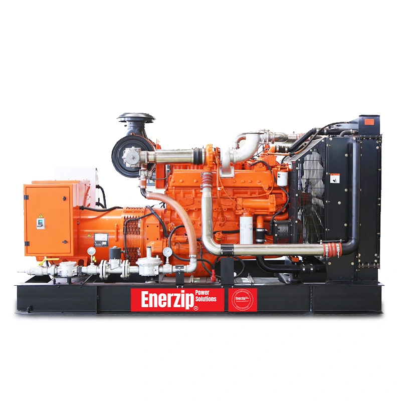
- Natural Gas Generator Sets
- Biogas Generator Sets
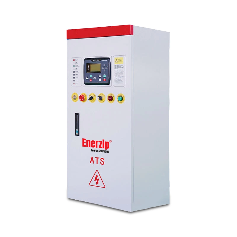
- Automatic Transfer Switches (ATS)
Note: This article provides an engineering workflow reference. Final requirements and acceptance targets should be confirmed against local codes, site drawings, equipment tolerances, and the agreed FAT/SAT scope.