How to use: Treat this as a “supplier alignment tool.” If you complete the key sections and ask vendors to respond with a compliance matrix, you dramatically reduce scope gaps, commissioning surprises, and post-delivery disputes.
Note: Rating definitions and interpretations can vary across manufacturers and markets. Always confirm the exact rating basis in the supplier’s datasheet and the agreed FAT/SAT test scope.
About the Reviewing Team
Enerzip Applications & Integration Team supports EPC contractors, distributors, and industrial users by translating load profiles, duty cycles,
and site constraints into actionable generator configurations. We typically validate assumptions through FAT/SAT planning, staged load pick-up logic,
and site airflow/cooling checks—because most project failures happen at transfer, motor start, or high-ambient operation.
Why EPC Generator RFQs Fail
Most EPC generator RFQs don’t fail because teams “forgot the kVA.” They fail because the RFQ does not define what must happen during the critical moments:
utility transfer, staged load pick-up, largest motor starts, and high-ambient operation. When those moments are undefined, suppliers guess—and the project pays later.
Common RFQ outcomes when scope is unclear
- Everyone quotes a different size because the load pick-up strategy is not defined.
- Cooling is underestimated because ambient and enclosure airflow path are missing.
- ATS timing and re-acceleration behavior are ignored until commissioning.
- UPS/rectifier behavior is assumed, which creates step-load trips.
- Noise limits are specified without distance/measurement method, causing disputes.
What a “project-grade” generator specification checklist does
- Turns “backup power” into a measurable performance statement. For general reference on technical declarations used in generating-set specification and design, readers may also review ISO 8528-7.
- Defines control boundaries (ATS / load shedding / paralleling) so vendors quote the same scope.
- Captures site constraints early (ambient, altitude, dust, enclosure pressure drop).
- Links rating language to acceptance tests (FAT/SAT) so the contract is harder to misunderstand.
Enerzip Field Note (why disputes happen): In post-delivery disputes, the root cause is often not “insufficient kW,” but an undefined test condition. A supplier may pass steady-state load yet fail on site because ATS transfer timing, motor re-acceleration, or enclosure airflow was never specified.
Practical fix: Put acceptance targets in the RFQ (example: voltage dip ≤ 15% for ≤ 1–2 s during the worst motor start event for PLC-heavy sites) and link them to FAT/SAT scope.
How to Use This Checklist in an EPC Workflow
Recommended EPC usage
- Concept / early budget: complete Sections A–F with “assumptions stated.”
- Procurement RFQ: complete Sections A–I; request a compliance matrix from suppliers.
- Pre-FAT: finalize acceptance targets, staged load pick-up plan, and documentation list.
- Site commissioning: use the SAT checklist to validate transfer behavior, start sequence, and thermal margin.
How suppliers should respond
- Return a line-by-line compliance table (Comply / Deviate / Optional / Not included).
- State assumptions explicitly (ambient, altitude, fuel quality window, step-load behavior).
- Attach datasheets and single-line drawings aligned with the stated control scope.
Specification Checklist (A–J)
Tip: The fastest way to make quotes comparable is to define (1) the “moment of truth” events, (2) staged load pick-up logic, and (3) site derating inputs.
A) Project definition & performance intent
A1. Facility / application
- Industry: manufacturing / utility / water & wastewater / mining / telecom / hospital / data center / oil & gas
- Operational goal: protect critical operations, reduce downtime risk, control total cost of ownership
- Single site or multi-site rollout?
A2. Availability target
- Architecture: single set / N+1 / 2N / parallel modular expansion
- Downtime tolerance: acceptable outage duration
- Maintenance strategy: can the site accept maintenance shutdowns?
A3. “Moment of truth” definition
- Transfer type: open transition (break-before-make) or closed transition (make-before-break), if permitted by utility/interlocks
- Expected transfer time and load pick-up sequence
- Worst-case event: largest motor start after transfer? UPS step load? combined?
Enerzip Field Note (performance intent): RFQs that only specify “kVA rating” but do not define transfer behavior often procure the wrong solution.
Verification hook: Add an “event list” to the RFQ: (1) ATS transfer, (2) largest motor start, (3) UPS pick-up behavior, (4) thermal operation at design ambient.
B) Electrical fundamentals
B1. System voltage, frequency, and wiring
- Rated voltage: e.g., 400/230V, 480/277V, 11kV (if HV project)
- Frequency: 50Hz or 60Hz
- Phase & wiring: 3P4W / 3P3W / 1P2W
- Power factor basis for rating (commonly 0.8 unless specified otherwise)
B2. Grounding / earthing and neutral
- Grounding system basis: TN-S / TT / IT / solidly grounded / resistance grounded (as applicable)
- Neutral switching requirements at ATS (if required)
- Earth fault protection philosophy
B3. Power quality expectations
- Sensitive loads present? (PLC, VFD, medical devices, servers, instrumentation)
- UPS type and behavior: step load vs ramp, input harmonics, generator compatibility notes
- Voltage regulation expectation (define if needed; otherwise request supplier standard)
Note: Rating definitions and interpretations may vary by manufacturer and region; require vendors to state the rating basis and proposed test scope.
C) Load profile & motor starting
C1. Provide a load list with start method
Minimum load list fields:
- Load tag / name; type (motor / VFD motor / UPS / lighting / heater / transformer / rectifier)
- Quantity
- Running kW and PF (or running kVA)
- Starting method: DOL / star-delta / soft starter / VFD
- Starting current or starting kVA (preferred from motor datasheet)
- Duty: always-on / intermittent / emergency-only
- Priority: must-run / delay-start / shedable
C2. Define the largest “single event”
- Largest motor start (kW/HP, start method, acceleration time)
- Largest step load (UPS/rectifier, HVAC group, process block)
- Re-acceleration risk after transfer (motors that coast down and restart together)
C3. Staged start sequence (RFQ must include)
- Essential controls & lighting first
- Largest motor alone (if practical)
- Secondary groups with time delays
- Non-critical loads last
Enerzip Field Note (motor starts): If the RFQ does not state “largest motor start method,” vendors will assume differently and quotes become non-comparable.
Practical detail: Define an acceptable voltage dip target for the largest start event (example: ≤ 15% for ≤ 2 s for PLC-heavy sites) and confirm it during FAT/SAT.
D) Duty cycle & rating language (ESP/PRP/COP with careful wording)
D1. Define operating category in plain language
- Emergency standby only (rare outages) vs frequent backup (weak grid) vs continuous/baseload
- Expected annual runtime hours and longest continuous run
- Typical load level during runtime (e.g., 40–70% average, occasional peaks)
D2. Use rating terms carefully
- Require supplier to state which rating category they are quoting (ESP/PRP/continuous-type or equivalent).
- Require kVA and kW shown together under a stated PF basis.
- Require site conditions for which rating is valid (ambient, altitude).
- Require proposed FAT/SAT test scope for validation.
Important: ISO 8528 terminology is widely used, but rating definitions and interpretations may vary by manufacturer and region. Confirm with datasheet and test scope.
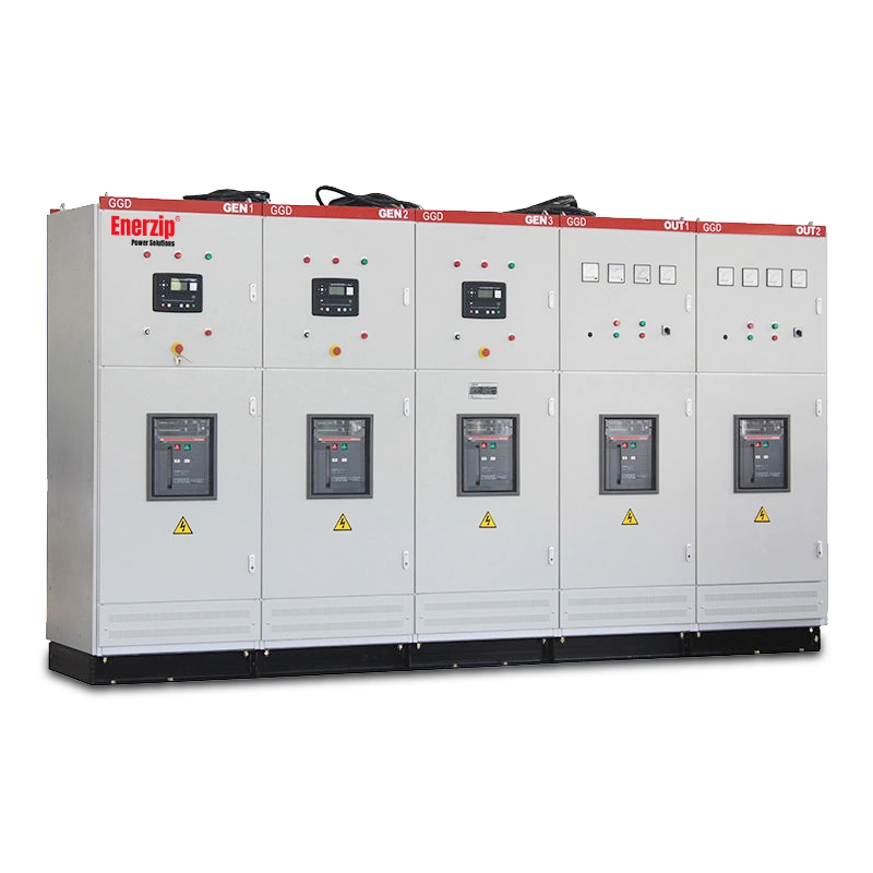
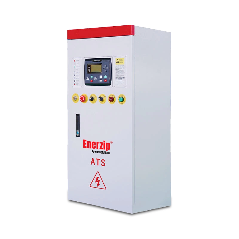
E) Controls scope: ATS, load shedding, synchronization, and parallel logic
E1. ATS scope
- ATS rating (A), poles, neutral switching requirement. For general reference on transfer switching equipment used to ensure continuity of supply, readers may also review IEC 60947-6-1.
- Transfer type: open transition vs closed transition (if applicable)
- Transfer delay, re-transfer delay, re-transfer inhibit (if needed)
- Return-to-utility behavior (manual/auto, cooldown, unload)
E2. Load shedding logic
- Tier 1: must-run (safety, controls, critical operations)
- Tier 2: delay-start (pumps, compressors, staged HVAC)
- Tier 3: shedable (non-critical loads)
- Shedding triggers: underfrequency, overload, manual priority selection
E3. Paralleling and synchronization
- Parallel quantity now and future expansion plan
- Synchronizing controller scope and power management functions
- Load sharing strategy (kW/kVAr sharing where applicable)
- Black start logic (if a plant microgrid is involved)
E4. Remote monitoring and communications
- Protocols: Modbus (RTU/TCP), SNMP, dry contacts, Ethernet gateways
- Alarm list and event history requirements
- Remote start/stop permissions and cybersecurity constraints (if any)
Enerzip Field Note (controls prevent oversizing): If you define staged load pick-up and shedding tiers, you often reduce alternator oversizing and improve stability.
Verification hook: Ask suppliers to propose a start sequence schedule (time delays) and show how it meets your voltage/frequency dip targets during the largest event.
F) Site conditions & derating: ambient, altitude, enclosure, dust, fuel
F1. Ambient temperature and altitude
- Design ambient: typical and peak (e.g., 40–50°C)
- Altitude and barometric conditions (if highland site)
- Expected temperature rise inside enclosure/container
F2. Installation environment
- Indoor / outdoor / rooftop / container compound
- Dust/sand, humidity, corrosion risk (coastal vs inland)
- Rain, flooding risk, drainage requirements
F3. Enclosure airflow and cooling path
- Airflow direction constraints (front-to-back vs side discharge)
- Allowable pressure drop in ducting (if ducts are used)
- Recirculation prevention requirements
F4. Fuel conditions (diesel / natural gas / biogas)
- Fuel type and availability constraints
- For gas/biogas: methane range, pressure range, contaminant limits as defined by project
- Fuel storage scope (day tank / base tank / external tank) and autonomy hours
Enerzip Field Note (hot sites fail on airflow): In high-ambient regions, many issues come from airflow path and recirculation—not nameplate kVA.
Practical SAT record: Require recording of coolant temperature at stable load, radiator inlet/outlet air temperature, and enclosure internal temperature during a representative run.
G) Mechanical & packaging scope: canopy, container, skid, fuel system
G1. Configuration
- Open skid / silent canopy / weatherproof canopy / containerized power house
- Service access requirements (side doors, maintenance clearance)
- Lift points, forklift pockets, base frame requirements
G2. Noise specification
- Target noise in dB(A)
- Distance (e.g., 7 m) and measurement condition (free field vs reflective)
- Operating load condition for measurement (e.g., 75% or 100%)
G3. Fuel system scope
- Base tank size and autonomy hours
- Day tank and transfer pump scope (if required)
- Fuel filtration / water separator requirements (if applicable)
G4. Optional accessories that change project integration
- Battery chargers, block heaters, space heaters for alternator/enclosure
- Fire detection/suppression interface for containerized systems (if required)
- External emergency stop stations
H) Switchgear, protection, and integration boundaries
H1. Breaker and protection requirements
- Main breaker type: MCCB/ACB, ratings, trip settings philosophy
- Protection functions: over/under V, over/under Hz, overload, short circuit coordination (project-dependent)
- Earth fault protection philosophy and measurement method
H2. Switchboard / distribution boundary
- Is the supplier providing only the genset, or also the LV switchboard?
- Interlocks between ATS, generator breaker, and utility breaker
- Metering: kW, kVA, kVAr, PF, kWh, event logs
H3. Cabling and terminations
- Cable entry direction and gland plate requirements
- Termination lugs and busbar expectations (project-dependent)
- Grounding and bonding points on skid/container
I) Testing & documentation: FAT/SAT deliverables that prevent disputes
I1. FAT (Factory Acceptance Test) scope
- Visual inspection, wiring check, labeling verification
- Sensor and alarm function checks
- Protection checks and emergency stop validation
- Control logic: start/stop, cooldown, ATS interface (as applicable)
- Load test (when required): staged load steps to evaluate dip and recovery
I2. SAT (Site Acceptance Test / commissioning) scope
- Transfer test (utility-to-generator, generator-to-utility)
- Start sequence validation (staged motors, delays, shedding)
- Worst-case event test (largest motor start after transfer, UPS pick-up behavior)
- Thermal verification at representative ambient and airflow conditions
I3. Documentation package
- Datasheets: engine, alternator, controller, ATS/switchgear (as supplied)
- Single-line diagram (SLD)
- Wiring diagrams and terminal schedules
- GA drawings: dimensions, weight, lifting points, service clearance
- Test reports: FAT results, insulation checks (if performed), load bank results (if performed)
- O&M manuals and spare parts list
Enerzip Field Note (acceptance targets): Define acceptance targets in the RFQ and enforce them in FAT/SAT to reduce “it passed in factory but failed on site” risk.
Example targets (confirm per project): Voltage dip ≤ 15% for ≤ 1–2 s during worst motor start; frequency dip ≤ 10% with recovery within ≤ 5 s after largest step load.
J) Logistics, spares, warranty, and after-sales expectations
J1. Packaging and delivery
- Delivery format: open skid / canopy / container
- Seaworthy packing, anti-corrosion protection, shock indicators (if needed)
- Shipping/customs documentation (as required)
J2. Commissioning support
- Remote commissioning support or on-site support requirement
- Training scope for operators and maintenance team
J3. Spares and consumables
- Recommended spare parts list (one-year / two-year / critical spares)
- Consumables list and maintenance interval assumptions
J4. Warranty statement
- Warranty period and operating hour definition
- Response expectations and escalation route
- Clarify what is covered under system integration vs component warranty (as applicable)
Copy/Paste RFQ Template
Instruction: Copy the block below into your RFQ email or procurement document. Ask suppliers to respond with a compliance matrix and state all assumptions.
RFQ TITLE: Generator Specification Checklist (EPC Project)
1) Project overview
- Facility/application:
- Location / installation type (indoor/outdoor/container):
- Availability target (single / N+1 / 2N / parallel expansion):
- Duty cycle (annual hours, longest continuous run):
- Critical “moment of truth” events to validate (ATS transfer, largest motor start, UPS pick-up, thermal run):
2) Electrical requirements
- Voltage / frequency / phase / wiring:
- Grounding / neutral requirements:
- PF basis for rating:
- Sensitive loads / UPS details (step vs ramp, harmonics, compatibility notes):
3) Load profile & motor starting
- Provide load list with running kW/kVA, PF, start method (DOL/star-delta/soft starter/VFD), starting current/kVA, duty, priority
- Largest motor details (kW/HP, start method, accel time)
- Largest step load details (UPS/rectifier behavior)
- Staged start sequence requirement (supplier to propose time delays)
4) Rating & duty statement
- Quoted rating category (ESP/PRP/continuous-type or equivalent)
- kVA and kW stated together under PF basis
- Validity conditions (ambient, altitude) and proposed derating assumptions
- Proposed acceptance test scope aligned with project events
5) Controls scope
- ATS scope (type, rating, poles, delays, neutral switching)
- Load shedding tiers and logic (Tier 1/2/3)
- Paralleling/synchronization scope (if applicable)
- Remote monitoring protocols and alarm list
6) Site conditions
- Design ambient and peak ambient
- Altitude
- Dust/sand/humidity/corrosion risks
- Enclosure/container airflow constraints (ducting, pressure drop, recirculation avoidance)
- Fuel type and constraints (diesel / natural gas / biogas; quality window if applicable)
7) Mechanical / packaging
- Configuration: open / canopy / weatherproof / container
- Noise requirement (dB(A), distance, test load)
- Fuel storage and autonomy hours
- Accessories (heaters, chargers, E-stop stations, etc.)
8) Switchgear and integration boundaries
- Main breaker type and settings philosophy
- Interlocks with utility and ATS
- Switchboard scope boundary (by EPC or supplier)
9) Testing & deliverables
- FAT scope (functional + protections + optional load bank steps)
- SAT scope (transfer test, staged starts, worst-case event, thermal run)
- Documentation package: SLD, wiring diagrams, GA, manuals, test reports, spares list
10) Supplier response format
- Compliance matrix (Comply / Deviate / Optional / Not included)
- Statement of assumptions and exclusions
- Datasheets + drawings attached
Annexes
Annex A — Load list headings
| Field | Example / Notes |
|---|---|
| Load Tag / Name | P-101 Process Pump |
| Type | Motor / VFD Motor / UPS / Lighting / Heater / Other |
| Qty | 1 / 2 / 3… |
| Voltage / Phase / Frequency | 400V / 3P / 50Hz |
| Running kW / PF / Running kVA | kVA can be calculated if PF known |
| Running current (A) | If available |
| Start method | DOL / Star-Delta / Soft Starter / VFD |
| Starting current or Starting kVA | Prefer motor datasheet |
| Start duration (s) | Acceleration time |
| Duty | Always / Intermittent / Emergency-only |
| Priority | Must-run / Delay-start / Shedable |
| Notes | Re-acceleration, harmonics, special constraints |
Annex B — Acceptance targets
- Voltage dip: ≤ 15% for ≤ 1–2 seconds during worst start event (confirm with PLC/UPS tolerance)
- Frequency dip: ≤ 10% with recovery within ≤ 5 seconds after largest step load
- Thermal: coolant temperature stable within acceptable range at representative ambient and airflow conditions
- ATS: transfer logic and staged restart behave as specified (no “all motors restart together”)
Annex C — Drawing / document list
- SLD (single-line diagram)
- GA drawings (dimensions, weight, lifting points, service clearance)
- Wiring diagrams + terminal schedules
- Controller I/O list (if project requires)
- FAT report + SAT checklist
- O&M manuals + spare parts list
FAQ
1) Why do EPC quotes vary so much for the same “kVA” requirement?
Because the RFQ usually does not define the load pick-up strategy, ATS behavior, motor start method, and site derating conditions.
Suppliers apply different assumptions, producing different kVA and different scope.
2) Do I need to specify acceptance targets like voltage dip and frequency recovery?
If your site has PLC/VFD/UPS loads or large motor starts, yes. It makes quotes comparable and gives a measurable commissioning goal.
Targets must match the actual tolerance of your equipment.
3) Should the RFQ include FAT/SAT requirements?
Yes. Linking rating language to FAT/SAT scope reduces disputes and increases reliability.
A “pass” should mean the system passed the events that matter (transfer, staged starts, thermal run), not only steady load.
4) How do I avoid oversizing without risking trips?
Define staged starts, shedding tiers, ATS timing, and worst-case event tests. Many projects can reduce size and improve stability with better controls rather than larger nameplate.
Next Step
If you share (1) your load list (Excel), (2) site ambient/altitude, (3) duty cycle intent, and (4) ATS/control scope, Enerzip can turn this checklist into a project-ready RFQ package
and a supplier comparison matrix—so you can procure a reliable standby generator system with fewer surprises.
Related Resources
- How to Size an Industrial Backup Generator
- Genset FAT/SAT Testing & Inspection Steps + Warranty Support
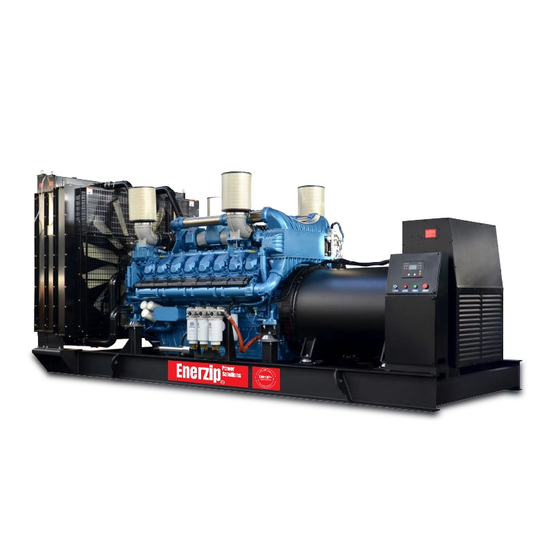
- Diesel Generator Sets
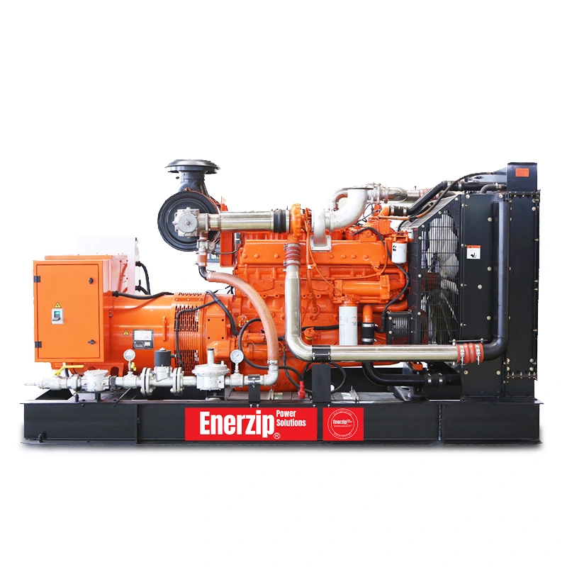
- Natural Gas Generator Sets
- Biogas Generator Sets
- Automatic Transfer Switches (ATS)
Note: This checklist is an engineering workflow guide. Final requirements should be confirmed against local codes, site drawings, equipment tolerances, and the agreed FAT/SAT test scope.