Cooling and Ventilation Guide: High-Ambient Derating, Enclosure Airflow, and Acceptance Testing
RFQ-ready generator cooling checklist: define ambient/altitude, limit external pressure drop (ΔPext), prevent recirculation, and verify with SAT thermal logs.
Reviewed by: Enerzip Power Technology (Weifang) Co., Ltd. – Applications & Integration Team
Last updated: 03-Feb-2026
Update policy: Reviewed when common high-ambient assumptions (40–50°C), enclosure/container airflow practices, or FAT/SAT acceptance expectations change.
Scope: Practical cooling and ventilation engineering for industrial generator systems (diesel / natural gas / biogas), focused on measurable airflow constraints, derating triggers, and RFQ-ready acceptance targets.
Executive Summary
Genset cooling and ventilation is the practical difference between a standby generator system that runs for hours at a hot site and one that trips after transfer. This guide shows how to translate high ambient temperature (40–50°C), canopy/container airflow resistance, duct pressure drop, and recirculation risk into measurable RFQ requirements—and then prove them through FAT/SAT thermal logging before those issues become commissioning rework or downtime. This workflow helps EPC teams convert site constraints into RFQ-ready acceptance criteria.
About the Reviewing Team
Enerzip Applications & Integration Team supports EPC contractors, distributors, and industrial users by translating load profiles, duty cycles, and site constraints into actionable generator configurations. We validate assumptions through FAT/SAT planning, staged load pick-up logic, and site airflow/cooling checks—because many real project failures are triggered by transfer events, motor re-acceleration, step loads, or high-ambient operation inside restrictive enclosures.
Assumptions & Limitations
- This is a project workflow guide. It does not replace OEM datasheets, local codes, or site engineering drawings.
- All numeric targets here are practical engineering starting points. Final limits must be confirmed against engine OEM alarm thresholds, radiator/fan capability, enclosure restriction, and the required outage runtime.
- Cooling performance depends on ambient + altitude + airflow restriction + recirculation. A “50°C tropical” claim is not meaningful unless validity conditions and allowable external restriction are stated. For general reference on engine power declaration under stated reference conditions, readers may also review ISO 3046-1.
Why Genset Cooling & Ventilation Failures Happen
Many generator projects fail thermally even when the kVA rating looks correct. Cooling is a system behavior, not a nameplate number. A unit can pass a factory load run and still overheat on site if the enclosure/room airflow path is restrictive or if hot discharge air recirculates back into the radiator intake.
Most disputes are not about rated kW. They are about conditions that were never defined:
- Ambient and altitude (hot & high reduces margin)
- Airflow path (where intake air comes from, where discharge goes)
- External pressure drop ΔPext (louvers/ducts/baffles/screens add restriction)
- Recirculation risk (hot discharge short-circuiting back to intake)
- Acceptance evidence (what temperatures were logged, for how long, and where probes were placed)
Field reality: In hot regions, many site failures come from airflow path and recirculation—not from insufficient kVA. A unit may run stable for 10–15 minutes and alarm after 1–3 hours once the enclosure/room heat-soaks. In practice, issues are most visible after transfer, when airflow restriction and recirculation combine with step loads.
High-Ambient Derating: What Really Changes at 40–50°C
High ambient temperature affects both engine and alternator. The practical problem is that the cooling system must reject more heat while intake air is already hot—and often restricted by canopy/container layouts, louvers, or ductwork.
What to Define in RFQs
- Design ambient: typical and peak (baseline: 45°C typical / 50°C peak)
- Altitude: meters above sea level (baseline: 1000 m)
- Longest continuous run: expected outage runtime (baseline: 8 hours; extend to 24 hours if required)
- Packaging: open skid vs canopy vs container vs indoor room vs rooftop (baseline worst case: canopy / container)
- Airflow constraints: ducted discharge + louvers + dust/sand screens + acoustic baffles (baseline included below)
Derating Is Not One Number
Derating depends on engine platform, radiator size, fan capability, and total external restriction. For procurement, do not accept a generic curve only. Require the supplier to state:
- Rated output validity conditions: ambient / altitude / airflow assumptions
- Maximum allowable external restriction for the radiator/fan air path (ΔPext in Pa) at the stated reference plane
- Thermal acceptance method: what will be logged during SAT (temperatures, duration, probe locations, evidence format)
RFQ Boundary Statement
Cooling performance and available output are valid only under the specified ambient, altitude, and airflow constraints. Supplier shall declare the maximum allowable external pressure drop ΔPext (Pa) for the radiator/fan air path and provide a compliance statement against the project’s louver/duct configuration. Final acceptance is based on SAT thermal logging under representative site conditions.
The Airflow Problem: External Restriction and Recirculation
Definitions
External pressure drop ΔPext (Pa) in this guide means: the total additional pressure drop imposed by louvers/ducts/screens/baffles in the radiator/fan air path, referenced at the radiator/fan interface, reported using the supplier’s stated method (Pa). Always request the supplier’s definition and reference plane in writing.
1) External Restriction (ΔPext) in Practical Terms
A radiator fan is designed to move a certain airflow at a certain static pressure. Louvers, duct turns, baffles, and screens add restriction. As restriction rises, airflow drops. For practical reference on airflow losses caused by inlet and outlet duct conditions, readers may also review AMCA guidance on fan system effect. Less airflow means less heat rejection and higher coolant temperature.
- EPC action: request the supplier’s allowable ΔPext limit (Pa) and keep the louver/duct design under it.
- Supplier action: state required airflow and allowable ΔPext, then confirm compliance against the proposed layout.
RFQ must-have sentence:
Supplier shall provide (1) required radiator airflow (m³/h) and (2) maximum allowable external pressure drop ΔPext (Pa) for the radiator/fan air path at the stated reference plane. EPC shall provide a louver/duct ΔP estimate (Pa), including a fouling allowance, for supplier compliance confirmation.
2) Recirculation: The Silent Killer
Recirculation happens when hot discharge air returns to the radiator intake. It can occur even with “large airflow” if discharge is short-circuited around the enclosure or trapped in a confined yard.
Common triggers: short discharge path, low discharge height, nearby walls, wrong discharge direction, intake and discharge on the same façade without separation.
Best indicator: compare radiator intake air temperature vs true ambient. If intake is consistently higher, recirculation is likely.
Quick diagnostic: If ambient is 45°C but radiator intake measures 52–55°C during operation, the unit is not “running at 45°C.” It is running at 52–55°C intake—usually due to recirculation. This is an airflow design issue, not a kVA issue.
Measurement Points
- Ambient (°C): in shade, away from discharge airflow (ideally 5–10 m from discharge and not inside a heat plume zone)
- Radiator intake (°C): 0.3–0.5 m upstream of radiator intake plane
- Radiator discharge (°C): at discharge outlet zone using a consistent position
- Room/container internal (°C): mid-height, away from discharge jet and away from radiator face
- Evidence requirement: probe photos + simple layout sketch included in SAT report
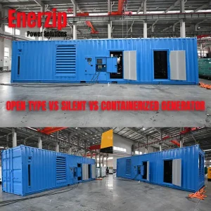
Installation Patterns (trade-offs)
Pattern 1 — Open skid
- Strength: best thermal margin
- Risks: weather/dust/corrosion exposure; noise treatment handled differently
Pattern 2 — Silent canopy
- Strength: noise control and weather protection
- Risks: intake/exhaust restriction, internal recirculation, service access constraints
- Must specify: airflow + ΔPext limits + SAT thermal logging + “normal operating state” (doors/vents position) during test
Pattern 3 — Containerized power house
- Strength: security, standardized logistics, optional switchgear room
- Risks: ΔPext + recirculation common; heat-soak appears after hours
- Must-have: defined ventilation design + supplier-stated ΔPext limit + SAT thermal run duration + evidence logs
Pattern 4 — Indoor generator room
- Strength: protected environment
- Risks: room temperature rise, insufficient fresh air, discharge short-circuit, poor clearance
- Must-have: ventilation design + discharge routing to avoid plume re-entry + room temperature rise targets
RFQ-Ready Ventilation Requirements
Example Baseline Inputs
- Installation type: Containerized power house (worst airflow case) with intake louvers + discharge duct
- Design ambient: 45°C typical / 50°C peak
- Altitude: 1000 m
- Longest continuous runtime during outage: 8 hours (extend to 24 hours if required)
- Airflow constraints: intake louvers + dust/sand screen + acoustic baffles + discharge duct + insect mesh
- Noise baseline (common EPC requirement): 75 dB(A) @ 7 m @ 75% load (project to confirm)
- EPC duct/louver ΔP target (design goal): ≤ 60 Pa + fouling allowance 20 Pa → expected total ≤ 80 Pa
RFQ Quick-Fill Bullets
- Design ambient: 45°C typical / 50°C peak
- Airflow requirement: ≥ 35,000 m³/h per 1000 kW (radiator airflow at rated fan speed; vendor to state basis)
- Max allowable external restriction: ΔPext ≤ 100 Pa (at radiator/fan interface; reference plane defined by vendor)
- Recirculation KPI: radiator intake rise ≤ 5°C above ambient (warning at 8°C) during stabilized steady hold
- SAT evidence: 2-hour hold @ 70% rated kW + probe photos + controller trends + 10-min logs
Minimum Site Inputs
- Location + installation type (open / canopy / container / indoor room / rooftop)
- Design ambient (typical / peak) and altitude
- Longest continuous runtime at hot ambient (hours)
- Noise requirement (dB(A), distance, operating load condition)
- Airflow constraints (ducting, louvers, sand screens, acoustic baffles)
What Suppliers Must Return
- Cooling validity statement: output validity at specified ambient/altitude + derating assumptions
- Airflow + restriction limit: required radiator airflow (m³/h) and max allowable ΔPext (Pa) with definition/reference plane
- Recirculation prevention: intake/discharge arrangement + required clearances + discharge direction notes
- SAT thermal plan: run duration, load level in kW, probe locations, evidence format
Acceptance Targets + FAT/SAT
Important Note: kW vs kVA for Test Load
Test load is expressed in kW (real power). If the genset rating is in kVA, convert using the site power factor (PF) and the agreed acceptance load level. Always document PF and kW/kVA in the SAT report.
Thermal Acceptance Targets
| Event / Item | Acceptance Target | How to Test (FAT / SAT) | Instrumentation / Evidence | Notes |
|---|---|---|---|---|
| Thermal run at high ambient | No high-temp alarm, no protective shutdown, and no power limitation (if applicable) during 2 hours @ 70% rated kW; target ambient ≥ 45°C | SAT: hold load steady; doors/vents in normal operating state | Controller trends + temp log every 10 min + probe photos | 2 hours catches heat-soak issues; extend to 4–8h if runtime requires |
| When site ambient is below target | If ambient < 45°C, acceptance based on stable trends and margin to OEM limits using an agreed substitute method | SAT: extend hold to 4 hours and verify stabilization; use intake-vs-ambient KPI; pass/fail by OEM alarm margin | Trend logs + ambient/intake evidence + written method agreement | Prevents “test impossible” disputes; OEM alarm threshold remains the boundary |
| Coolant stability | Coolant stabilizes with no rising trend; maintain at least 5°C below OEM high-temp alarm (example: alarm 103°C → target ≤ 98°C) | FAT basic check; SAT confirms under real airflow restriction | Controller coolant trend + handheld cross-check | OEM alarm threshold is the true limit |
| Intake air vs ambient (recirculation check) | Intake temperature rise ≤ 5°C above ambient during steady load hold (warning at 8°C) | SAT: ambient away from discharge; intake near radiator face | Two probes + photos + layout sketch | Measured after stabilization; probes fixed and documented |
| Room/container internal rise | Internal rise ≤ 10°C over ambient (warning at 15°C) during thermal hold | SAT: probe mid-height away from discharge jet; log through hold | Room temp log + ventilation fan status | Protects auxiliaries/controls from heat-soak trips |
| External restriction compliance | EPC louver/duct ΔP estimate ≤ supplier allowable; baseline expected total 80 Pa (60 Pa design + 20 Pa fouling) and must be ≤ vendor allowable (example allowable 100 Pa) | FAT: document review; SAT: confirm stable temperature trends | Supplier ΔPext declaration + EPC ΔP estimate + SAT evidence | Mandatory for canopy/container/room installs |
| Discharge–intake ΔT (diagnostic) | Typical steady-load discharge–intake ΔT 15–25°C (diagnostic only) | SAT: measure discharge at consistent outlet point | Temperature log + probe photos | ΔT varies; do not use as pass/fail alone |
FAT: Cooling-Related Checks
- Verify radiator/fan rotation direction, fan staging (if any), thermostat function, and alarm threshold settings per OEM.
- Basic load run to confirm no immediate overheating and stable coolant trend.
- For canopy/container: confirm intake/discharge openings match drawings and are not blocked by accessories.
- Deliverables: supplier must state airflow assumptions + required airflow (m³/h) + ΔPext limit (Pa) + SAT thermal acceptance plan.
SAT: What Proves Readiness at Site
- Verify ventilation path: clear intake, clear discharge, no short-circuit airflow.
- Run a representative thermal hold: minimum 2 hours @ 70% rated kW (extend if runtime requires).
- Record evidence: ambient vs intake, discharge, coolant trend, room/enclosure temperature + probe photos.
Thermal Evidence Log Template (SAT)
Use consistent probe points and include photos showing locations. Log at least every 10 minutes for a 2-hour hold (or per project requirement). Record PF and load in kW.
| Timestamp | Load (kW) | Ambient (°C) | Intake (°C) | Discharge (°C) | Coolant (°C) | Room/Enclosure (°C) | Notes |
|---|---|---|---|---|---|---|---|
| 00:00 | 560 | 45 | 49 | 68 | 90 | 54 | Start hold, normal vents |
| 00:10 | 560 | 45 | 50 | 69 | 91 | 55 | Stable |
| 00:30 | 560 | 46 | 51 | 70 | 93 | 56 | No alarms |
| 01:00 | 560 | 46 | 51 | 71 | 95 | 57 | Intake rise 5°C (pass) |
| 01:30 | 560 | 45 | 50 | 69 | 96 | 56 | Stable trend |
| 02:00 | 560 | 45 | 49 | 68 | 97 | 55 | Hold complete, pass |
Quick interpretation:
- Intake close to ambient (≤ 5°C rise) suggests low recirculation
- Coolant stabilizing ≥ 5°C below alarm suggests adequate margin
- Room rise within target suggests ventilation is sufficient for auxiliaries and serviceability
Common Failures and Practical Fixes
Failure 1 — Overheat after 1–3 hours despite “rated power”
- Typical causes: heat soak, discharge short-circuit, blocked louvers, excessive restriction, poor yard airflow
- Fix: redesign intake/discharge separation; reduce restriction; add discharge height; verify intake vs ambient rise during steady hold
Failure 2 — Canopy/container runs hotter than expected
- Typical causes: acoustic baffles too restrictive, door state changes airflow, auxiliary heat trapped
- Fix: require airflow (m³/h) + ΔPext limit (Pa) in writing; validate via SAT logs and photos
Failure 3 — Recirculation in confined compounds
- Typical causes: walls close to discharge, multiple units discharging into each other, wind patterns ignored
- Fix: orient discharge away from walls; increase separation; consider chimney discharge; log intake vs ambient
Failure 4 — “Noise fix” creates thermal failure
- Typical causes: silencers/baffles added without restriction check
- Fix: treat noise & airflow as one design; require ΔPext compliance against the final restriction set
RFQ Checklist & Vendor Compliance Matrix
RFQ — Genset Cooling & Ventilation Requirements
- Site: Hot-region industrial site; containerized power house (intake louvers + discharge duct)
- Ambient: Typical / peak = 45 / 50 °C
- Altitude: 1000 m
- Runtime requirement: Longest continuous run = 8 hours
- Airflow constraints: louvers + dust/sand screen + acoustic baffles + discharge duct + insect mesh
- Noise: 75 dB(A) @ 7 m @ 75% load
Supplier must state:
- Output validity conditions (ambient/altitude) and derating assumptions
- Required radiator airflow (m³/h) and maximum allowable external restriction ΔPext (Pa) with definition/reference plane
- Recirculation prevention approach (intake/discharge arrangement + required clearances)
- Proposed SAT thermal run plan (duration, load level in kW, probe locations, evidence format)
Vendor Compliance Matrix
| Requirement | Project Target / Input | Vendor Statement | Comply / Deviate | Notes / Assumptions |
|---|---|---|---|---|
| Design ambient / altitude validity | 45°C typical / 50°C peak; 1000 m altitude | State guaranteed rating at these conditions (kW and kVA), rating class (Emergency Standby Power (ESP) / PRP / COP), PF basis, validity conditions, and attach OEM reference + offered cooling package configuration | Comply / Deviate | Must match OEM limits and offered radiator/fan package under declared ΔPext limit; state whether any protective power limiting applies |
| Required radiator airflow | Provide airflow in m³/h; baseline expectation: ≥ 35,000 m³/h per 1000 kW | Provide airflow requirement and basis (fan speed, radiator type, test/calculation method) | Comply / Deviate | Mandatory for canopy/container/room with louvers/ducting |
| Max allowable external restriction (ΔPext) | EPC ΔP target: ≤ 60 Pa + fouling 20 Pa → expected total ≤ 80 Pa | Declare max allowable ΔPext (Pa), define reference plane, and confirm compliance to EPC ΔP | Comply / Deviate | Include screens/baffles; provide ΔP budget if possible |
| Recirculation control | Intake not exposed to discharge plume; separation required | Describe airflow path + clearances + discharge direction; provide layout sketch | Comply / Deviate | Verify by intake vs ambient rise during stabilized steady hold |
| SAT thermal run evidence | 2 hours @ 70% rated kW; target ambient ≥ 45°C (preferred) | Confirm duration/load/probe points; deliver SAT report with trend logs + probe photos | Comply / Deviate | If ambient < 45°C, extend hold to 4 hours and accept by stabilized trends + OEM alarm margin |
| Intake vs ambient KPI | Pass: ≤ 5°C rise; Warning: 8°C | Accept measurement method; provide evidence in SAT report (photos + sketch) | Comply / Deviate | Most practical recirculation KPI |
| Room/container internal rise | Pass: ≤ 10°C; Warning: 15°C | Confirm ventilation assumptions and provide temperature log evidence | Comply / Deviate | Protects auxiliaries and avoids heat-soak trips |
Supplier response format: Compliance matrix (Comply / Deviate / Optional / Not included) + assumptions + drawings + proposed test method.
FAQ
1) Can a generator pass FAT but fail thermally on site?
Yes. Factory conditions rarely match site airflow restrictions. Without defined airflow constraints and SAT thermal evidence, a “pass” may only mean a short steady run under favorable conditions.
2) What is the fastest way to detect recirculation?
Measure radiator intake air temperature and compare it to true ambient measured away from discharge. If intake is consistently more than about 5°C above ambient during steady operation, recirculation is likely.
3) How long should a thermal run be?
For hot sites or enclosed installations, 2 hours is a practical minimum to catch heat-soak behavior. Extend to 4–8 hours when sites require longer outage runtime.
4) Should EPC specify external restriction limits?
EPC should require the supplier to state the radiator/fan allowable ΔPext and confirm compliance against the final louver/duct layout. This prevents late disputes caused by “silent fixes” that restrict airflow.
Related Resources
- Industrial Generator TCO: Why “Cheap” Gensets Cost More
- Generator Specification Checklist for EPC Projects
- Backup Power Architecture for Data Centers & Hospitals
- Genset FAT/SAT Testing & Commissioning Guide
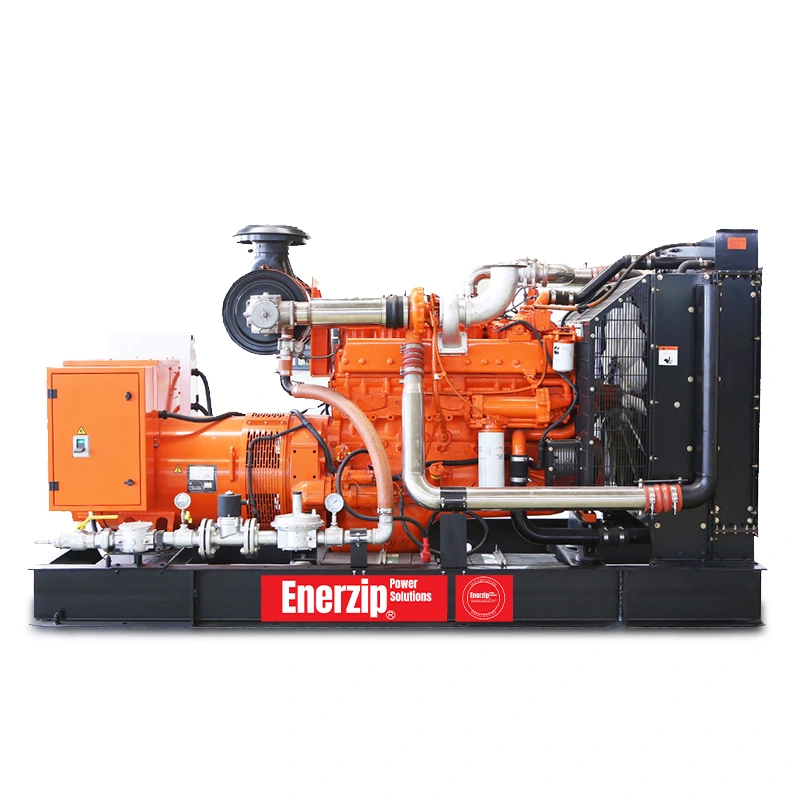
- Diesel Generator Sets
- Natural Gas Generator Sets
- Biogas Generator Sets
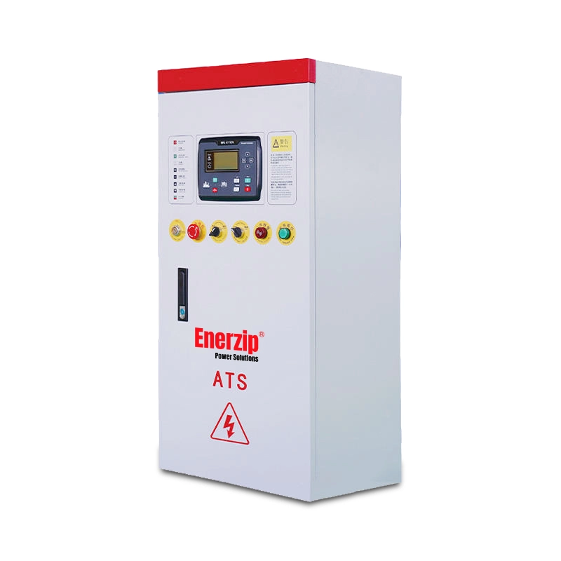
- Automatic Transfer Switches (ATS)
Note
This guide is an engineering workflow reference. Final requirements and acceptance targets should be confirmed against local codes, site drawings, equipment tolerances, and the agreed acceptance test scope (FAT/SAT).