About the reviewing team
Enerzip Applications & Integration Team supports EPC contractors, distributors, and industrial users by translating load profiles, duty cycles, and site constraints into actionable standby generator system configurations. We typically validate assumptions through RFQ compliance matrices, event-based acceptance targets, staged load pick-up logic, and site airflow/cooling checks—because most real project failures happen at transfer, motor start, step load, or high-ambient operation.
Practical outputs we commonly deliver during projects: (1) event list + acceptance targets, (2) staged pick-up schedule, (3) load shedding tiers, (4) FAT/SAT checklist aligned with the event list, and (5) supplier comparison matrix (Comply / Deviate / Optional / Not included).
Why critical-load backup power is different
For simple standby sites, teams often size a standby generator by adding up running kW and applying margin. For data centers and hospitals, that approach is incomplete because the system is judged during a few short, stressful moments—not during steady-state operation.
Those “moment of truth” events include:
- Utility loss: the site voltage collapses and loads react immediately.
- Transfer event: the ATS (or switchgear) determines when and how loads reconnect.
- Load pick-up: UPS systems, rectifiers, chillers, pumps, and fans may return together if staging is not defined.
- Step load & recovery: frequency and voltage dips must remain inside what servers, PLCs, drives, and medical equipment can tolerate.
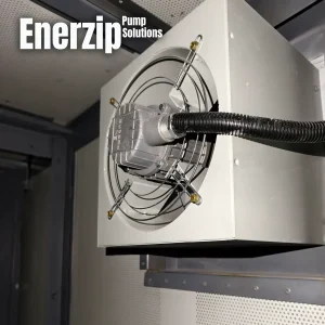
- Thermal reality: high ambient temperature, canopy/container airflow resistance, and recirculation decide whether the system can run for hours.
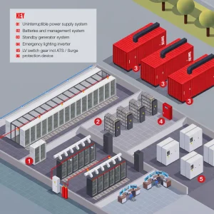
In other words, critical standby power is not “a box that makes kVA.” It is an integrated architecture: ATS + UPS (if used) + generator(s) + switchgear + controls + ventilation + commissioning tests. If any part of that chain is undefined in an RFQ, suppliers guess—and the project pays later in commissioning rework and reliability risk.
Enerzip Field Note (why projects fail): Post-delivery disputes rarely start with “kW is insufficient.” They start with an undefined event: ATS timing, UPS recharge step load, the largest motor re-acceleration after transfer, or an enclosure airflow path that was never specified. A genset can pass a steady-state load test and still fail the site’s event behavior.
Verifiable habit: Put a short event list into the RFQ (utility loss → transfer → staged pick-up → worst motor start → UPS recharge behavior → thermal run) and link each event to FAT/SAT acceptance checks. It forces comparable quotes and reduces commissioning surprises.
Define critical load tiers before you buy equipment
A reliable industrial standby generator solution begins with load classification. Not every circuit is equally critical, and forcing “everything” to pick up at once is the fastest way to oversize, trip on transients, or both. A practical tier model is shown below.
| Tier | Purpose | Typical loads (examples) | Pickup behavior | Notes for RFQ |
|---|---|---|---|---|
| Tier 1 | Life safety / mission-critical controls | Emergency lighting, life safety alarms, critical control systems, essential medical circuits (hospital-specific), data center EPMS/BMS core monitoring | Immediate or fastest pickup allowed | Define “must-run” list; define ride-through requirement if sensitive |
| Tier 2 | Essential operations (delay-start allowed) | Cooling pumps, chillers (staged), ventilation fans, compressed air blocks, process utilities required within minutes | Staged start with time delays | Require supplier to propose staged pickup schedule |
| Tier 3 | Non-critical / shedable | Comfort HVAC, non-essential lighting, admin loads, non-critical workshops | Shed during recovery; optional pickup later | Define shedding triggers (underfrequency/overload) and manual priorities |
Tiering gives you control levers: staged pick-up, load shedding, and coordinated recovery after transfer. Without tiers, the system behaves like “everything returns at once,” and the largest transient becomes unpredictable.
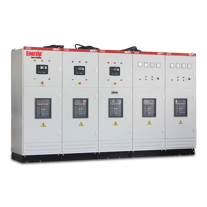
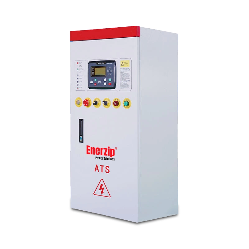
ATS vs UPS: what each one actually solves
ATS (Automatic Transfer Switch): switching and reconnection logic
An ATS is not just an accessory. In many standby generator systems, it defines the reconnection moment and therefore the site’s real transient behavior. These ATS choices change the architecture:
- Open transition vs closed transition: break-before-make vs make-before-break (where permitted by utility and interlocks).
- Neutral switching: depends on grounding philosophy and local practice; define it explicitly in the RFQ.
- Transfer delays and re-transfer logic: settings decide whether loads re-accelerate together after transfer.
- Multiple ATS vs centralized switchgear: topology affects staging and selective pickup control.
UPS: ride-through and stability for sensitive electronic loads
A UPS exists mainly to bridge the gap between utility loss and stable generator output, and to provide conditioned power to sensitive loads. But UPS systems can create generator challenges if coordination is not defined:
- Recharge demand: after running on battery, many UPS systems draw a recharge step load unless configured for controlled ramp.
- Rectifier behavior and kVA demand: some rectifiers can increase apparent power requirement and add harmonics.
- Coordination matters: the best UPS in a critical backup power architecture is not “the biggest,” but the one configured to cooperate during transitions.
Practical takeaway: ATS solves switching; UPS solves ride-through and sensitive load stability. A robust architecture uses each intentionally instead of assuming “ATS only” or “UPS fixes everything.”
UPS recharge step load: what to ask in an RFQ
One of the most common hidden causes of nuisance trips in a critical standby generator system is UPS behavior after transfer. The UPS may be stable during battery discharge, but then it begins recharge and rectifier operation in a way that looks like a step load to the generator.
UPS & rectifier inputs that make proposals comparable
Ask your UPS vendor (or your internal electrical team) for the following inputs, and include them in the generator RFQ as a “coordination annex.”
| UPS/Rectifier item | What to request | Why it matters to generator sizing and stability | How to verify (FAT/SAT) |
|---|---|---|---|
| Ride-through time | Battery autonomy at critical load (minutes) | Defines allowed transfer window and generator start stabilization time | SAT: simulate utility loss, confirm no IT/critical drop |
| Recharge strategy | Step vs ramp; maximum recharge kW limit; configurable ramp rate | Recharge can create a large step load after transfer | SAT: monitor kW pickup and frequency nadir during recharge start |
| Input power factor & harmonics | PF range and THDi at typical loads | Affects kVA demand, heating, and generator voltage stability | FAT/SAT: record kVA, PF, and harmonic alarms if applicable |
| Bypass behavior | Static bypass trigger logic and transfer behavior | Unexpected bypass can create sudden kVA changes | SAT: confirm bypass events are logged and understood |
| Load type behind UPS | IT/server, medical electronics, imaging, PLC controls, etc. | Different loads have different dip tolerance and restart behavior | Define acceptance targets per tier |
Enerzip Field Note (verifiable detail): When the UPS “recharge ramp” is undefined, commissioning teams often discover the real step load only during the first integrated test. A simple improvement is to define the recharge limit (kW) and ramp behavior in the RFQ, then verify during SAT by trending (1) ATS close timestamp, (2) UPS input kW ramp, (3) minimum frequency, and (4) recovery time.
Measurement tip: Record voltage as line-to-line (L-L) on the bus after the ATS/switchgear, and record frequency at the same measurement point to keep data consistent.
Four proven architecture patterns (with trade-offs)
Below are common patterns used in critical facilities. There is no universal best choice—only what fits your uptime target, downtime cost, site constraints, and budget. Use these patterns to structure RFQs and prevent “scope mismatch.”
| Pattern | Best for | Strength | Typical risks if not specified | RFQ must-define |
|---|---|---|---|---|
| 1) ATS + standby generator (minimal UPS) | Industrial sites with limited sensitive electronics | Lowest complexity; lower CAPEX | Sensitive loads may drop during transfer; second transient trips | ATS timing, motor restart staging, acceptance targets |
| 2) UPS for critical electronic loads + generator for duration | Data center IT loads; hospital critical electronics | Ride-through protects sensitive loads | UPS recharge step load; rectifier kVA demand and harmonics | Recharge behavior, ramp limits, event-based SAT tests |
| 3) Tiered ATS network + staged start + load shedding | Mixed loads: motors + electronics + HVAC blocks | Stability without oversizing; predictable recovery | Undefined control boundary; unclear shedding triggers | Pickup schedule, shedding tiers, monitoring/event logs |
| 4) Parallel generators (N+1 optional) + critical switchgear | High uptime targets; large step loads; growth | Higher availability; better step-load acceptance | Protection coordination and control complexity | Synchronizing scope, load sharing method, SAT evidence logs |
Design shortcut: If your biggest problem is ride-through, UPS architecture and configuration matter most. If your biggest problem is step load and motor re-acceleration after transfer, staged pickup + shedding + paralleling often matters more than buying a larger single unit.
Procurement shortcut: Ask suppliers to state which pattern they are quoting and to return a compliance matrix. Otherwise, proposals may look similar on kVA but differ on what they actually include.
Data center vs hospital: what changes in architecture
Even when both are “critical facilities,” data centers and hospitals often differ in load shape, ride-through expectations, and commissioning priorities. Your RFQ and acceptance targets should reflect those differences.
| Topic | Data center (typical focus) | Hospital (typical focus) | What to write in RFQ |
|---|---|---|---|
| Ride-through dependency | UPS is central for IT loads; recharge behavior is critical | UPS may exist on selected circuits; life safety circuits and essential clinical loads dominate | Define which tiers require UPS ride-through and how UPS recharge is controlled |
| Step load drivers | UPS recharge + rectifiers + cooling blocks | Motor groups, ventilation, essential pumps; sometimes imaging/critical electronics | Define largest step event and motor re-acceleration scenario |
| Transfer sensitivity | IT equipment and network core controllers are dip-sensitive | Selected medical devices/circuits can be sensitive; life safety behavior is priority | Define event-based acceptance targets aligned with equipment tolerance |
| Commissioning evidence | Trend logs: voltage sag, frequency nadir, UPS input ramp, breaker close sequence | Event verification: ATS behavior, staged start, essential services continuity, alarms | Require SAT record set (timestamps + min V/Hz + thermal record) |
Important caution: Hospitals and data centers can have site-specific electrical codes, grounding philosophies, and critical-load definitions. This guide is an engineering workflow. Final requirements should be confirmed against local codes, site drawings, and the tolerance of your PLC/UPS/VFD/medical equipment.
Paralleling and N+1: availability and step-load strength
Two generator proposals with the same total kVA can behave very differently depending on whether they are single-set or paralleled. A modular parallel architecture can reduce downtime risk and improve transient performance—especially where the largest step load is significant.
When paralleling improves outcomes
- High downtime cost: a single failure event is expensive (service penalties, patient risk, operational loss).
- Large step loads: UPS recharge blocks, big HVAC groups, motor starts, or re-acceleration behavior.
- Maintenance without full loss of backup: the facility cannot drop to “no backup” during service.
- Future load growth: modular expansion is more predictable than replacing one oversized set.
N+1 vs 2N in practical terms
- N+1: enough capacity to carry the critical load even with one unit out of service (availability-oriented).
- 2N: two independent paths sized for full critical load (higher CAPEX; used where redundancy philosophy requires it).
Enerzip Field Note (what to log during commissioning): For paralleled systems, the most useful evidence after a trip is an event log aligned to the event list: transfer timestamp, each breaker close time, kW/kVAr sharing trend, frequency nadir, voltage sag depth, and recovery time. This turns arguments into data.
Practical record: Capture minimum frequency, minimum voltage (line-to-line), and recovery time during the largest step event at a consistent measurement point (post-ATS/switchgear bus).
Transfer timing, motor re-acceleration, and the second transient
Many teams focus on the first transient (utility loss). In real sites, the second transient is often worse: after the transfer, motors that coasted down attempt to re-accelerate, and UPS systems may begin recharging. If everything happens at once, a standby genset that looked “big enough” on paper can still trip.
Why motor re-acceleration after transfer causes trips
- Motors demand high current while they recover speed.
- Multiple motors can restart together if controls do not stage restarts.
- Contactors and VFDs may behave differently after a dip than in normal starts.
- Combined events (motor restart + UPS recharge) can look like one large step load.
Engineering levers that reduce the second transient
- Staged restart: interlocks + time delays for motor groups (Tier 2 and Tier 3).
- UPS recharge control: ramp limits and delayed recharge start if permitted.
- Load shedding tiers: shed non-critical blocks during recovery to protect frequency.
- Paralleling: modular capacity improves step-load acceptance and stability.
Acceptance targets and FAT/SAT: how to buy fewer surprises
Critical facilities should not “hope” the system works. They should define measurable acceptance targets and test them. This does not require quoting any standard text. It requires you to state what success looks like during real events, then verify through FAT/SAT scope aligned with those events.
Acceptance targets (examples you can adapt)
Targets must match your equipment tolerance. The numbers below are example starting points often used in PLC/IT-heavy sites, but you should confirm with your actual PLC, UPS, drive, and medical equipment manufacturers.
- Voltage dip target: define allowable dip depth and duration for the worst motor start event (example: ≤ 15% dip for ≤ 1–2 seconds).
- Frequency dip & recovery: define nadir and recovery time for the largest step load (example: ≤ 10% dip with recovery within ≤ 5 seconds).
- Thermal stability: stable coolant temperature and enclosure/internal temperature at representative ambient and airflow conditions.
- Transfer logic behavior: staged pick-up behaves as specified (no “all motors restart together”).
Caution: Acceptance target definitions can vary by project and by equipment tolerance. Confirm targets against site protection philosophy and the tolerance of your PLC/UPS/VFD/medical equipment. This prevents misunderstandings and avoids treating guidance text as “standard language.”
Event list template (the fastest way to make quotes comparable)
Use the table below as an RFQ annex. It converts “backup power” into measurable events and a verifiable test plan.
| Event | Trigger / scenario | Acceptance target (example) | Measurement point | Verification method | Evidence to submit |
|---|---|---|---|---|---|
| Utility loss | Simulated utility outage | No critical-load drop (per tier plan) | Post-ATS/switchgear bus; UPS output (if applicable) | SAT integrated test | Timestamp log + alarms + UPS status |
| ATS transfer | Open/closed transition per design | Transfer time within defined window | Post-ATS bus (L-L voltage & frequency) | SAT test with event recording | Transfer timestamps + min V/Hz |
| Largest motor start after transfer | Worst-case restart / re-acceleration | Voltage dip & duration within tolerance | Post-ATS bus; motor starter input | SAT staged restart test | Min voltage + dip duration + recovery time |
| UPS recharge step load | Recharge begins after battery discharge | Frequency nadir & recovery within tolerance | UPS input kW/kVA + post-ATS bus frequency | SAT test with trend logging | Trend: ATS close → UPS kW ramp → min Hz |
| Thermal run | Representative ambient / airflow constraints | Stable coolant & enclosure temperature | Coolant temp; radiator inlet/outlet air; enclosure temp | SAT thermal verification | Temperature record set + photos |
FAT and SAT: what matters for architecture
- FAT (Factory Acceptance Test): protection and alarm checks (over/under V & Hz, overspeed, emergency stop), control sequence verification (start/stop, cooldown, breaker logic, ATS interface where applicable), and optional staged step loads to evaluate dip and recovery for sensitive sites.
- SAT (Site Acceptance Test): utility loss simulation and transfer verification, staged motor restart and load shedding validation, worst-case event tests aligned with the event list, and thermal verification with real airflow constraints.
Simple win for “authority”: Require suppliers to submit a compliance matrix that includes the event list, acceptance targets, measurement points, and the test method proposed to verify each event. This is how you buy fewer surprises.
RFQ-ready checklist (copy/paste)
Copy the block below into your procurement document and ask vendors to respond with a compliance matrix.
RFQ — Critical Backup Power Architecture (Data Center / Hospital)

1) Project intent
- Facility type (data center / hospital / mixed critical site):
- Uptime target (single / N+1 / 2N) and downtime tolerance:
- Duty cycle (standby vs frequent operation), longest continuous run:
- Define the event list to validate (utility loss, ATS transfer, largest motor re-acceleration, UPS recharge behavior, thermal run):

2) Electrical basics
- Voltage / frequency / phase / wiring:
- Grounding philosophy and neutral switching requirement:
- PF basis for rating:
- Sensitive loads present (servers/PLC/VFD/medical devices) and tolerance notes:

3) Load tiers & load list
- Tier 1 must-run, Tier 2 delay-start, Tier 3 shedable:
- Provide load list with start methods (DOL/star-delta/soft starter/VFD) and starting current/kVA:
- Largest motor details (kW/HP, start method, acceleration time):
- Largest step load details (UPS/rectifier pickup or recharge behavior):

4) ATS scope
- ATS type, rating, poles, neutral switching:
- Open vs closed transition (if applicable):
- Transfer delays, re-transfer logic, return-to-utility behavior:
- Multi-ATS vs switchgear topology (if relevant):

5) UPS coordination (if used)
- Ride-through requirement (minutes):
- Recharge behavior (step vs ramp), maximum recharge kW, ramp settings:
- Rectifier PF and THDi, generator compatibility notes:
- Bypass behavior and logging requirements:

6) Controls scope
- Staged pick-up schedule (supplier to propose delays):
- Load shedding tiers and triggers (underfrequency/overload/manual priority):
- Monitoring, alarm list, event logs, trending requirements:

7) Paralleling (if used)
- Number of units now, future expansion plan:
- Synchronizing/switchgear scope, load sharing expectations:
- Black start / island mode requirement (if applicable):
- Evidence logs required during SAT (timestamps, min V/Hz, kW/kVAr sharing trend):

8) Site conditions
- Design ambient and peak ambient:
- Altitude:
- Indoor/outdoor, dust/humidity/corrosion risks:
- Canopy/container airflow constraints (ducting, pressure drop, recirculation avoidance):

9) Acceptance targets & FAT/SAT scope
- Event list + acceptance targets (example targets must be confirmed against equipment tolerance):
- Measurement points (post-ATS bus L-L voltage & frequency, UPS input trend if applicable):
- FAT scope: protections + logic + optional staged step loads:
- SAT scope: integrated events + staged restart + worst-case step + thermal run:
- Evidence package required (trend logs, timestamps, test report, photos of measurement points):

Supplier response format
- Compliance matrix (Comply / Deviate / Optional / Not included)
- Statement of assumptions and exclusions
- Drawings + datasheets + proposed test method per event list
FAQ
1) Is UPS always required for data centers and hospitals?
Not always for every load, but for sensitive electronic loads, ride-through is commonly needed because ATS transfer is not instantaneous. A practical approach is to use UPS where ride-through is necessary, and use staged pick-up + load shedding to stabilize the rest of the site.
2) Why do systems trip after transfer even when running kW is below rating?
Because the worst moment is not steady running. It is motor re-acceleration, UPS recharge, and step loads. Architecture choices (staging, shedding, paralleling) often solve this more effectively than simply increasing nameplate kVA.
3) What should we test to reduce commissioning surprises?
Test the event list: transfer behavior, staged restarts, the largest motor start after transfer, UPS pick-up/recharge behavior (if used), and thermal stability with real airflow constraints. Then log minimum voltage/frequency and recovery time at a defined measurement point.
4) When is N+1 worth the added complexity?
When downtime cost is high, step loads are large, maintenance cannot remove all backup capacity, or future load growth is expected. A modular parallel design can reduce risk and often improves step-load acceptance.
Next step
If you share (1) your tiered load list (Excel), (2) duty cycle intent (standby vs frequent operation), (3) site ambient/altitude and installation constraints, and (4) ATS/UPS/paralleling scope expectations, Enerzip can help translate it into an RFQ-ready architecture package: staged pick-up schedule, load shedding tiers, suggested generator sizing range, and FAT/SAT acceptance targets aligned with your real “moment of truth” events.
Related resources (internal links)
- How to Size an Industrial Backup Generator (kW vs kVA, ESP/PRP)
- Generator Specification Checklist for EPC Projects (RFQ-ready)
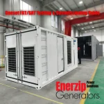
- Genset FAT/SAT Testing & Inspection Steps + Warranty Support
- Diesel Generator Sets
- Natural Gas Generator Sets
- Biogas Generator Sets
- Automatic Transfer Switches (ATS)
Note: This article is an engineering workflow guide. Final requirements should be confirmed against local codes, site drawings, equipment tolerance (PLC/UPS/VFD/medical equipment), and the agreed acceptance test scope (FAT/SAT).