Enerzip high voltage generators (medium-voltage generator sets) are engineered for large facilities where low-voltage distribution becomes costly or impractical. Medium-voltage generation at 3.3kV / 6.3kV (6.6kV) / 10.5kV / 11kV / 13.8kV can reduce current, minimize voltage drop, and cut copper cable size and heat loss—helping maintain stable voltage across long feeders and heavy motor-starting loads (project dependent).
Our portfolio covers 275–3750 kVA across six proven platforms (C / M / MS / P / W / Y Series), supporting data centers, mining, utilities, industrial parks, infrastructure, and microgrids—where MV switchgear protection, synchronization, and engineered packaging determine real uptime.
Features:
Enerzip’s High Voltage Generators portfolio typically spans 275–3750 kVA, with 3.3–13.8 kV-class output options (project dependent). Instead of selecting by kVA alone, we help match the right series and configuration based on duty cycle (ESP/PRP/COP per ISO 8528), load behavior (motor starting and load steps), site conditions (ambient / altitude / ventilation), and electrical integration scope (VCB switchgear, CT/PT metering, protection coordination, synchronization & load sharing)—reducing common MV project risks such as copper-intensive LV distribution, long-feeder voltage drop, thermal derating constraints, protection selectivity/setting mismatch, nuisance trips, and commissioning rework.
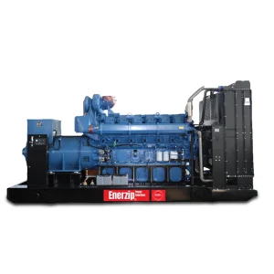
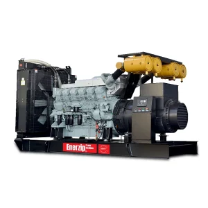
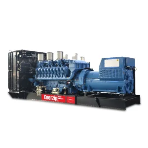
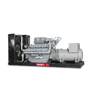
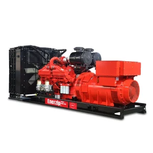
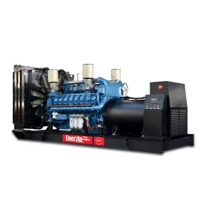
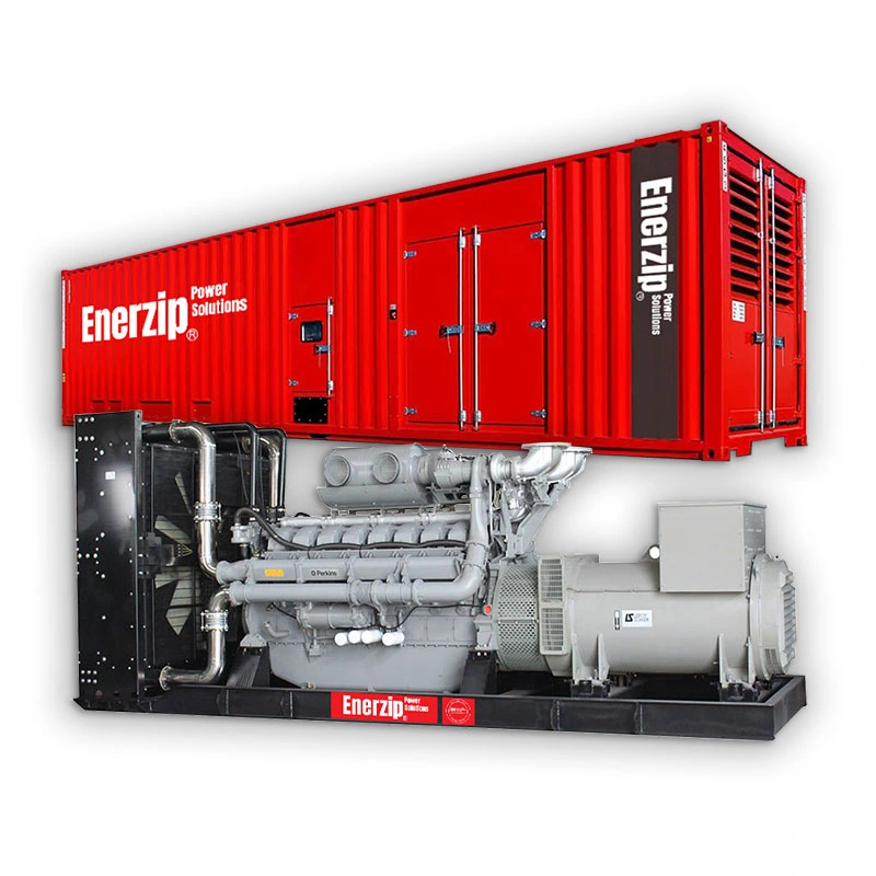
Enerzip supplies 3.3–13.8kV High Voltage Generators in open, silent/weatherproof, and containerized “Power House” formats (project dependent). Options include VCB switchgear, synchronization/paralleling, remote monitoring, and documentation support.
We support fast technical alignment and responsive quotation with standardized HV integration. Lead time varies by voltage level, protection/switchgear scope, and enclosure/container format.
Every HV genset is inspected for wiring & insulation integrity, VCB/protection logic readiness, load-step voltage/frequency stability (project dependent), and ventilation/thermal margin for enclosures/containers (project dependent).
24/7 support for selection, installation guidance, commissioning, and troubleshooting—including protection coordination, synchronizing plans, and FAT/SAT support.
High Voltage Generator projects are rarely “standard.” Real performance is defined by MV distribution strategy, protection integrity, step-load recovery, cooling/ventilation limits, and interface scope—not by kVA alone. That’s why Enerzip High Voltage Generators are configured based on how the site distributes power and how loads behave—so the system delivers stable megawatt-class output when uptime is non-negotiable.
In practice, MV generator systems commonly face:
Transmission efficiency & cable economics: correct MV selection (3.3/6.6/10.5/11/13.8kV) can reduce current, cable size, I²R losses, and electrical-room congestion (project dependent).
Protection & coordination complexity: HV requires defined boundaries between genset, VCB switchgear, relays, CT/PT, and site network—unclear scope often causes nuisance trips and commissioning delays.
Motor starting & large load steps: pumps, chillers, compressors, crushers, flood-control drives, and large HVAC loads create harsh transient events that demand proven step-load acceptance and fast recovery.
Cooling margin in hot and restricted sites: containers and silent enclosures raise airflow resistance; high ambient and dust can drive derating or overheating if ventilation isn’t engineered correctly.
Integration scope & acceptance requirements: synchronization, multi-unit plants, and microgrids need clear FAT/SAT logic, test points, and deliverables (project dependent).
To make selection faster and reduce mismatch, this category page follows a six-platform HV series strategy aligned with common duty profiles and project types:
M Series – High Voltage Generators — mission-critical HV for hyperscale data centers and semiconductor users where transient response and stability dominate.
C Series – High Voltage Generators — industrial-grade HV integration for predictable uptime and broad project compatibility (critical facilities, large standby/prime users).
MS Series – High Voltage Generators — compact footprint and high power density for space-constrained industrial and urban sites needing MV output.
P Series – High Voltage Generators — baseload-oriented HV solutions where maintainability and long-hour operation planning matter most.
Y Series – High Voltage Generators — heavy-duty torque and durability for infrastructure-heavy markets and rugged industrial duty.
W Series – High Voltage Generators — ROI-driven megawatt-class HV capacity for large-scale industrial expansion, mining, and utility-style deployments.
For deeper planning and faster quotation, you may also explore: HV Switchgear & Protection (VCB), Paralleling / Synchronization Solutions, Containerized “Power House” Packages, and a Genset Cooling & Ventilation Guide (high-ambient derating / enclosure airflow / acceptance testing).
What we typically review to recommend the right HV series/configuration: required kVA/kW, rating basis (ESP/PRP/COP), largest motor starting and load steps, site conditions (ambient / altitude / ventilation limits), voltage level and distribution distance, and integration scope (VCB protection / synchronization / remote monitoring)—so your High Voltage Generator performs predictably on site.
To avoid under- or over-engineering, we recommend sizing and configuration based on your voltage level, load profile, and operating mode:
Electrical requirement: required kVA/kW, voltage level (3.3–13.8kV), frequency (50/60Hz)
Load data: average/peak load, largest motor (kW/HP), largest load step (if any)
Operating mode: grid-parallel or island, ATS required or not, single or multi-unit (if any)
Site conditions: ambient temperature, altitude, enclosure type (open/canopy/container)
High voltage generator sets are most often used when a project runs on a medium-voltage (MV) distribution network and the loads are MW-class, spread over a large site, or dominated by large motors. By generating at 3.3kV / 6.6kV / 10kV / 11kV / 13.8kV, the system carries much lower current than LV, which helps reduce cable size, voltage drop, and distribution losses—especially for long-distance feeders. HV gensets are typically integrated with MV switchgear (VCB), protection relays, synchronization, and plant-level load management (project dependent).
Mining is one of the most common real-world HV genset scenarios because mines often operate 6.6kV or 11kV site networks with long cable runs and harsh conditions. HV generator sets are used to power:
Crushers, conveyors, mills, screens, flotation systems
Dewatering and slurry pumping
Remote workshops, camps, and auxiliary loads via MV feeders
Why HV is chosen here: mines need high motor-starting capability, stable voltage under step loads, and practical distribution across a wide area (project dependent).
In oil & gas, HV generator sets support sites where grid supply is weak/unavailable or where continuous operation is required. Typical loads include:
Gas compressors, pipeline booster stations
Process pumps, water injection, separation auxiliaries
Instrument air, utilities, and plant auxiliaries
These projects often demand multi-unit redundancy (N+1), planned maintenance without shutdown, and stable performance during large load changes (project dependent).
HV generator sets are commonly used where the primary loads are large pumps and the distribution is spread out:
Flood control pumping stations
Raw water intake and transfer pumping
Large irrigation districts and canal lift stations
In these sites, MV distribution is practical because pumps can be far from the power house. HV generation reduces voltage drop over distance and supports high starting torque requirements (project dependent).
Industries that cannot tolerate unexpected outages frequently use HV gensets as standby or prime power:
Cement plants (kiln fans, crushers, mills)
Steel and metallurgy (auxiliaries, rolling lines support)
Chemical and refining (critical pumps and utilities)
Large manufacturing campuses with MV distribution
HV gensets fit best when the plant already has MV switchgear rooms, and the generator can connect directly to the MV bus with proper protection and interlocks (project dependent).
Some large facilities use MV distribution to reduce congestion and transformer count across a campus:
Industrial parks and large commercial complexes
Airports, transport hubs, and large public infrastructure
Certain data center campuses that distribute at MV internally
In these cases, HV gensets can simplify the MV architecture by feeding the MV bus directly, and expansion is easier with staged multi-unit planning (project dependent).
HV generator sets are also used in professional power-plant-style deployments where the system requires:
Synchronization and load sharing across multiple units
Grid-parallel operation (export or peak shaving where permitted)
Microgrid operation with renewables and energy storage
Black-start capability (starting the system without utility supply)
These projects are protection- and control-intensive (sync check, reverse power, under/over V/Hz, earth fault schemes, etc.), so they depend heavily on the grid code and owner specification (project dependent).
Yes. For MV sites, it’s common to integrate the genset into an MV distribution system (e.g., 13.8kV campus networks are widely used, with MV switchgear and step-down points).
To quote correctly, we need: required kVA/kW, voltage (3.3/6.6/10/11/13.8kV), frequency, single-line diagram (SLD), and especially the MV switchgear/bus fault level and interface scope (genset-only vs. genset + VCB switchgear). MV generator installations typically define a protection zone from generator terminals to the first overcurrent device/switchgear bus.
For MV generator and interconnection protection, projects commonly specify a dedicated generator/interconnection relay plus required ANSI functions. Dedicated products exist specifically for generator and interconnection protection.
Typical functions (final list depends on grid code and owner spec) often include:
87 (generator differential), 40 (field loss) — frequently referenced as minimum protections in genset electrical design guidance
32 (reverse power) — commonly required to prevent motoring when paralleled
27/59 (under/over voltage), 81U/81O (under/over frequency) — commonly listed in utility interconnection requirements
25 (sync-check), 24 (V/Hz), plus phase/ground overcurrent and earth-fault elements (project dependent)
We don’t guess—this is engineered from your load profile. The key data we need: largest motor kW/HP, starting method (DOL / soft starter / VFD), estimated inrush current, and the largest load step.
For performance verification, many tenders reference ISO 8528-5 transient performance classes, which define voltage/frequency limits under load steps and recovery expectations.
In practice, ISO-based verification focuses on step-load testing, not an unrealistic “0–100% instant load jump.”
Based on your data, we may recommend: generator/engine sizing margin, alternator reactance selection, or changing starting method (e.g., VFD) if DOL starting would cause unacceptable dips (project dependent).
Yes—integrated MV switchgear with vacuum circuit breaker (VCB) is a common architecture for MV generator applications.
To size and select correctly, we need:
System voltage (e.g., 11kV or 13.8kV) and frequency
Required continuous current at generator full load
Required short-circuit withstand / interrupting rating (kA, seconds), based on your system study
CT/VT requirements for protection & metering (often dictated by the owner/utility)
This avoids over/under-rated switchgear and is essential for protection coordination.
Grid-parallel projects are driven by the local utility/grid code, so the RFQ must include the interconnection requirement document and the point of interconnection (POI) details. Utilities commonly require specific protective functions such as under/over voltage, under/over frequency, and reverse power (among others).
In some markets, protective relay settings must also respect ride-through requirements and coordination guidance (for example, NERC PRC-024 in North America focuses on generator voltage/frequency protective relay settings at the POI).
Our deliverables typically include: protection philosophy, relay function list, I/O mapping for SCADA (if required), and coordination inputs for the owner’s power system study (final settings approved by the EPC/utility, project dependent).
For genset acceptance, industry guidance commonly distinguishes between factory functional tests and optional acceptance tests (often witnessed by the customer).
A realistic MV project FAT/SAT package typically includes (project dependent):
Functional checks: controller protections, alarms, trip logic, emergency stop, sensor calibration
Synchronization checks (if paralleling), load sharing logic (if multi-unit)
Verification of transient performance against the specified class/criteria (often referenced to ISO 8528-5 step-load concepts)
MV switchgear/VCB: interlocks, breaker open/close logic, relay injection/verification (as required)
Documentation: GA drawings, wiring schematics, protection list, test reports, and commissioning checklist